

Introduction of TEDS for Load Cells
Transducer Electronics Datasheet, or TEDS for load cells, is something we are frequently asked about as, over the years, the topic has been of interest to many hoping to use a load cell with a chip in it and be able to hook it up to multiple meters, to hook up multiple load cells to a single meter, and others hoping to hook up a single load cell to a single meter without reading a 200-page user manual.
Introduced in the early 2000s, TEDS IEEE chips promised to revolutionize load cell application standardization and efficiency.
Load cells, essential for precise force and torque measurements in various industries, could have benefited from the plug-and-play functionality and streamlined data management facilitated by TEDS.
However, TEDS for Load Cells never took off how they should have.
There are multiple reasons, from the cost to implement, the increased calibration cost, incorrect implementation of the IEEE standard, and creation of proprietary and non-compliant standards such as "SigCal, " Signature Calibration," and "TEDs Enabled" that confused users.
This article aims to delve into the world of TEDS for load cells, uncovering the potential pros and cons, applications for TEDS for load cells, and considerations to help you decide whether TEDS is suitable for your organization.
Understanding TEDS for Load Cells:
Aligned with the IEEE 1451.4 standard, TEDS IEEE chips can offer a transformative approach to integrating load cells.
These chips are designed to embed essential information directly into load cells, providing a standardized data storage and retrieval method.
When looking for TEDS for load cells, one will want to look for "IEEE 1451.4 compliant". If not so labeled, the vendor should be contacted to verify compliance.
This is important because several manufacturers use terms like "TEDS Enabled" or "SigCal," which are not entirely or partially IEEE 1451.4 compliant versions.
TEDS Enabled, for example, only stores an identifier so the indicator can pull the S/N of the unit. Here, no calibration information is stored on the chip. Therefore, "TEDs enabled" load cells can neither talk to IEEE 1451.4 compliant meters nor other "TEDS enabled" meters except the one it was calibrated with.
IEEE 1451.4 TEDS is inherently a straightforward concept that can be fitted to new load cells or refitted to existing load cells. Implementation is via a simple memory chip. The chip is separate from the sensor bridge circuit, although some wiring connections may be shared. People are confused and think TEDs will calibrate the load cell, but it does not affect the bridge circuit. Instead, the memory chips store the information to allow the meter or DAQ to scale and linearize the output from the load cell.
Therefore, it eliminates the manual programming of the indicator from the front panel and often eliminates the need to read hundreds of pages in user manuals to set up the indicator.
Before diving into the templates' technical aspects, consider if a TEDSfor load cell system is the right choice for you.
Top Pros of TEDS for Load Cells:
- Plug-and-Play Simplicity: Effortless setup due to automatic configuration, saving time and reducing errors.
- Cost-Effective Efficiency: Standardized data format promotes interoperability and eliminates manual configuration efforts, minimizing operational costs.
- Enhanced Accuracy and Reliability: Embedded sensor details and calibration data prevent manual entry errors and ensure accurate load cell readings.
- Streamlined Data Management: Easier access and management of load cell information, including calibration data, for efficient data analysis.
- Increased Versatility and Safety: Interoperability across platforms and protection against incorrect settings or connections improve overall system flexibility and safety.
Sounds great, doesn't it, though there are also cons, which can be expensive to maintain.
Top 5 Cons of TEDS for Load Cells:
- Cost Implications: Integrating TEDS into load cells may involve additional costs, impacting organizations with existing load cell systems that require retrofitting. A chip can easily be embedded in the load cell or cable, though new indicators must be purchased. Typically, indicators with the ability to read and write TED templates are much more expensive.
- Limited Adoption and Compatibility: Despite IEEE standardization, not all meters may comply with the TEDS IEEE 1451. Many meters list TEDS-enabled, which means they only store the ID, not the calibration data, potentially affecting seamless interoperability in mixed systems.
- Complexity in Calibration: Integrating TEDS into load cells can introduce more calibration work for the calibration laboratory. For instance, load cells that are calibrated with a meter require an "As Received" calibration, then a separate calibration or run to obtain the raw values (likely mV/V), programming the TED chip, and then the "As Returned" verification. The cycle time is typically at least double for the calibration lab, which increases calibration costs.
- Meter Calibration: If one wants to establish metrological traceability, one must either pay for all of their readouts (indicators) to be calibrated that can read the TEDS for load cell chips or purchase more equipment, such as a high-end load cell simulator to calibrate all of their meters. Morehouse has an article on what is required to do this here.
- Data Security Concerns: TEDS IEEE chips raise concerns about embedded data security within load cells, necessitating measures to protect sensitive information.
Which side are you leaning towards now?
TEDS for Load Cells can undoubtedly lead to better efficiency gains, and the lure of using multiple load cells and only needing one calibrated meter with TEDS is appealing.
Despite the additional calibration cost, buying IEEE 1451.4 TEDs equipment can reduce costs for most customers. It also lets customers calibrate their indicators in-house by purchasing a high-load cell accuracy simulator.
Templates and How TEDS stores information.
IEEE has published a great resource with the tables shown found here.
Information stored on the IEEE 1451.4 standard memory chip is organized into four sections. The first two are required, and the last two are optional.
1)Basic Teds: Serial Number and other misc. information
2) Standard template: Stores the basic calibration data like output range, calibration date, force units, and excitation
Template 33 for mV/V load cell (unamplified), This template is typically a starting point as it stores information and is always required for a mV/V load cell.
Template 31 for 4-20mA or 0-20mA
Template 30 for voltage amplified. i.e. 0-5V, .5 to 10.5V, etc.
3)Linearization templates (optional)
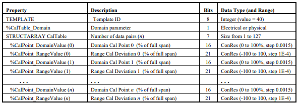
Template 40 provides linearization data piecewise (shown below on a graph as a 4 pt Span point option).
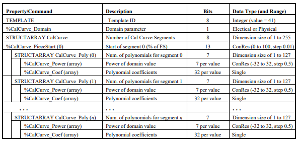
Template 41 provides linearization data via a curve fit polynomial. (Ideally suited for using calibration information from Morehouse ASTM E74 or ISO 376 certificates, as well as any Tension and Compression load cell)
The disadvantage of any of the above templates is the inability to characterize a load cell well in both tension and compression.
The programmed mode (compression or tension) will be closer to nominal, and the other mode will have large deviations unless the load cell has perfect symmetry between modes (this is rare).
There would be ways to install two different TEDS for load cell chips in one load cell.
If that option were chosen, the operator would typically have to use a switch to change between the two different chips.
4) User Teds: Additional memory space that can store miscellaneous information. The standard does not define this information. Therefore, if the load cell is to be used by multiple brands of indicators, it must not contain any necessary information.
Note: Compression and Tension points can be programmed, though it depends on the meter/DAQ’s firmware’s ability to make the proper interpretation and calculation.
It is highly recommended that any programming method be verified with the entire system and that the user understands how their meter interprets the data. A good validation method would be to send the system in with the meter and request a second calibration after the TEDS chip has been programmed.
Error Graphs Showing Different Options for Teds for Load Cells
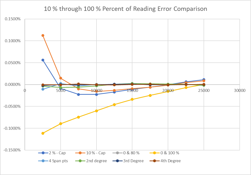
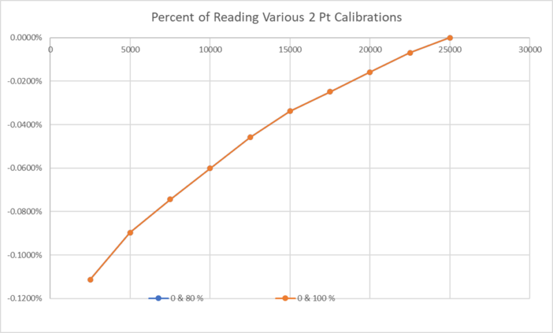
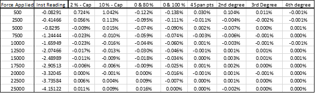
Figure 2breaks down 2 pt span calibration errors trying to span the device at 0 % & 80 % as well as 0 % & 100 %.
Our paper on converting mV/V into engineering units details the errors associated with a two-point calibration found here.
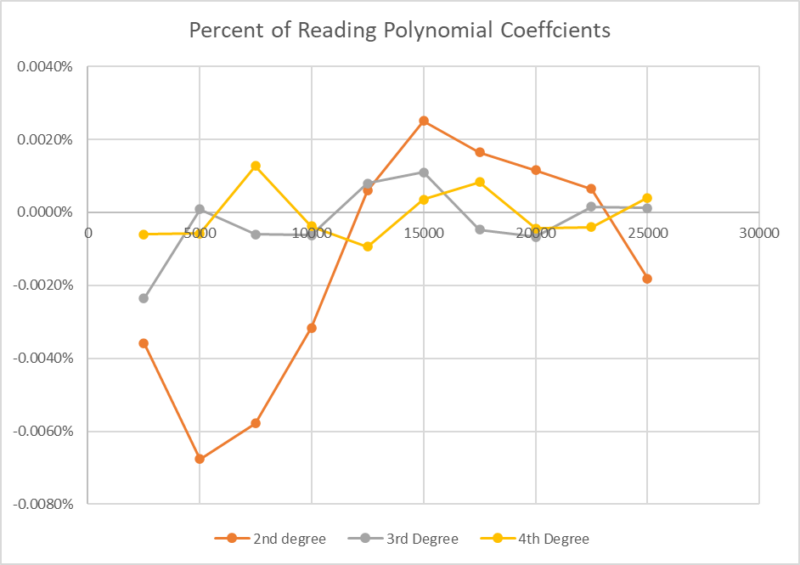
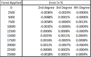
Since the errors from the other curves are high, the polynomial curves are tiny in the first graph and are harder to see. Figure 3 shows the errors from the polynomial curves from 2nd order through 4th order. This one clearly shows the 4th-order polynomial curve to have the slightest error with the lowest error at about four parts per million.
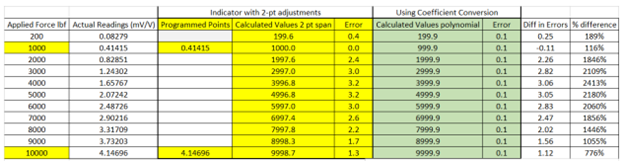
In Figure 4, we are pulling from our paper to show the difference in the same load cell in engineering units. One process produces an almost exact match, which is 0.001 % of full scale, while the other is 0.032 % . The worst point at 4,000 lbf has a difference of 3.06 lbf or 2413 %.
Do you think this TEDS template is a good fit for the likely increased calibration costs and readout upgrades required?
Template 40
Template 40 is nice as it offers more data points, though it has significant disadvantages compared with Template 41.
One of the more significant differences is calibration, assuming the end-user wants data reported in engineering units.
Any force-measuring system will drift over time and may require adjustments to bring the unit as close to nominal as possible. Templates 33 & 40 will likely create more calibration time and cost for the end-user to adjust their system constantly. Template 41 may also create more time if a calibration standard like ASTM E74 or ISO 376 is not followed.
If the desire is to have force readings as close to nominal as possible for all templates, three calibrations would be needed to make that happen.
Template 33 or 40 is typically for calibration in one mode, Compression or Tension.
- An "As Received" calibration in force units.
- A separate calibration to obtain A/D or mV/V values to reprogram the TEDS for load cells chip.
- An "As Returned" calibration will show the new values and the errors from the nominal.
Note: The price for this type of calibration is typically 1.5 times the cost of a regular calibration.
For Template 41, only one calibration would need to be performed and recorded in mV/V or A/D counts if a calibration standard like ASTM E74 or ISO 376 is not followed.
Template 41 criteria is typically for only one calibration in one mode, Compression or Tension.
- The load cell is always calibrated in mV/V without or without an indicator or A/D counts with an indicator.
- The calibration conforms to ASTM E74 or ISO 376 and generates coefficients.
- The TEDS for the load cell chip are programmed with coefficients.
- The end-user must be okay with all mV/V or A/D counts calibration reports.
Note: If without the indicator, whatever indicator is used must be calibrated, and measurement uncertainties must be accounted for.
Also, the calibration required doubles if the end-user wants the data in engineering units programmed as close as possible to nominal, lbf, kgf, N.
The generated coefficients could be plotted against the force applied, and any bias could then be accounted for in a Measurement Uncertainty Budget if the calibration was not performed using ASTM E74 or ISO 376, as those standards account for interpolation errors.
Looking at the error graphs and calibration costs, we believe there is a clear winner. It is Template 41, which offers the ability to store polynomial coefficients.
A polynomial is a mathematical expression of variables raised to non-negative integer powers combined through addition and subtraction.
These coefficients can be used to map the output on the load cell, which is sometimes called a calibration curve.
From our above graph and example, the coefficients can characterize the load cell's output so well that there is minimal error in using them.
In addition, TEDS for load cells template 41 can be simple for the calibration laboratory.
The laboratory generates all calibration certificates in some unit, typically mV/V, using the generated polynomial coefficients, programs the TEDs chip, and does the calibration if the calibration follows ASTM E74 or ISO 376.
When coefficients are used, the reference laboratory merely reads the actual mV/V values at the time of each calibration. Establishing the baseline or monitoring the results is much easier based on using mV/V.
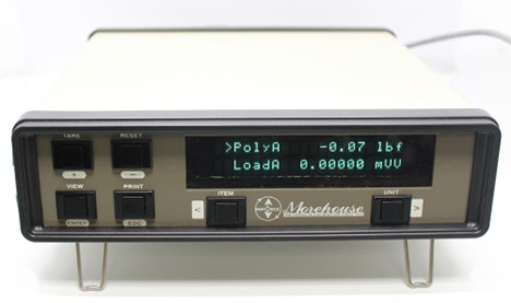
Morehouse Products with TEDS
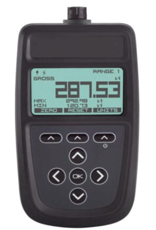
We have a PSDS which is the only under $ 1000.00 option we have seen that can read all three templates.
The manual for this device can be downloaded here.
From our manual on how the PSDS works:
All standard TEDS devices contain a basic 2-point calibration.
TEDS devices can also optionally hold multiple extended calibration tables; template ID=40 (multi-point calibration) or template ID=41 (polynomial calibration).
When you first connect a new TEDS device to the PSD a message will be displayed stating that a new TEDS device has been detected and that default settings have been used.
The first detected, valid calibration table from the TEDS device will be selected.
The user can select an alternative calibration table from the menu or Toolkit and this selection will be remembered and the table will be re-selected next time the device is plugged in.
Unlike the PSDS, the 4215 Plus does not come standard with the ability to read and write TED templates 33,40, & 41.
This upgrade can be added, though the lead time is typically longer.
The 4215 Plus comes standard with the ability to use polynomials internally making is a great choice to reap the benefits of using coefficients to generate a polynomial curve.
TEDS for Load Cells Conclusion:
So, in a nutshell, TEDS for load cells seemed like a fantastic idea with its plug-and-play promises and streamlined data management.
Introduced in the early 2000s, it was supposed to make force and torque measurements super easy. But guess what? It didn't take off as expected.
Why? There are pros, like efficiency gains and enhanced accuracy, but cons, like extra costs and limited adoption. It's like a seesaw between benefits and challenges.
Template 41 is promising—it stores polynomial coefficients.
It simplifies calibration, though it only works for a compression or tension load cell without an additional TEDS for a load cell chip and a physical switch.
But, and it is a big but, you need to weigh the benefits against the costs, such as more calibration standards and needing to calibrate every indicator that uses TEDS.
Ultimately, jumping on the TEDS bandwagon is like deciding if you want the latest 20-year-old gadget.
It might make things easier, though is it worth the price tag for equipment and more calibrations?
The future of TEDS for load cells is still a bit fuzzy, and whether it becomes a superstar or stays in the background depends on how well it fits into the real world of force and torque measurements.
If you are interested in TEDs for load cell meters or chips, Morehouse can have the discussions and make it happen.
It is a matter of finding the right solution for your needs and hopefully not breaking the bank.
Appendix Data used for graphs.
-Henry Zumbrun,
President of Morehouse Instrument Company
About Morehouse Instrument Company
Companies worldwide rely on Morehouse for accuracy and speed. The company turns around equipment in 7-10 business days so customers can return to work quickly and save money.
The York, PA-based company provides force and torque measurement products and services worldwide.
Morehouse Instrument Company, a trusted and accredited provider of force and torque measurement services for over 100 years, offers measurement uncertainties 10-50 times lower than the competition.
Morehouse helps commercial labs, government labs, and other organizations lower their measurement risk by lowering equipment uncertainties for torque and force measurement. Contact Morehouse at info@mhforce.com .
More Information From Morehouse
We believe in changing how people think about force and torque calibration in everything we do.
This includes setting expectations on load cell reliability and challenging the "just calibrate it" mentality by educating our customers on what matters and what causes significant errors.
We focus on reducing these errors and making our products simple and user-friendly.
This means your instruments will pass calibration more often and produce more precise measurements, giving you the confidence to focus on your business.
Companies around the globe rely on Morehouse for accuracy and speed.
Our measurement uncertainties are 10-50 times lower than the competition.
We turn around your equipment in 7-10 business days so you can return to work quickly, saving you money.
When you choose Morehouse, you're not just paying for a calibration service or a load cell.
You're investing in peace of mind, knowing your equipment is calibrated accurately and on time.
Contact Morehouse at info@mhforce.com to learn more about our calibration services and load cell products.
Email us if you ever want to chat or have questions about a blog.
We love talking about this stuff.
Our YouTube channel has videos on various force and torque calibration topics here.

