

Understanding ISO 376
Our last blog focused on the difference between ISO 376 and ASTM E74. That blog was a comparison between the major differences when comparing both standards and can be found here. What we hope to do with this blog is go into a bit more detail and explain the ISO 376:2011 Metallic materials — Calibration of force-proving instruments used for the verification of uniaxial testing machines standard. The ISO 376 standard is used worldwide, and it is a requirement for anyone calibrating in accordance with ISO 7500.
If ISO 7500 is the requirement, then calibration needs to be performed in accordance with ISO 376 on the force-proving instruments used to certify the tensile machine. It is also the generally accepted force standard for most of the countries outside of North America for the calibration of force-proving instruments such as load cells, proving rings, dynamometers, and other instruments used to calibrate similar types of instruments.
Characteristics of Force-Proving Instruments
ISO 376 characterizes force-proving instruments per section 6.1 Identification by stating “All the elements of the force-proving instrument (including the cables for electrical connection) shall be individually and uniquely identified, e.g. by the name of the manufacturer, the model, and the serial number. For the force transducer, the maximum working force shall be indicated.” The standard then goes on to address the application of force in section 6.2 by stating “The force transducer and its loading fittings shall be designed so as to ensure axial application of force, whether in tension or compression.”
Then in section 7.1 ISO 376 further states to ensure “that the attachment system of the force-proving instrument allows axial application of the force when the instrument is used for tensile testing; that there is no interaction between the force transducer and its support on the calibration machine when the instrument is used for compression testing.”
ISO 376 stresses the importance of keeping the line of force pure, free from eccentric forces as a key component to calibrating the instrument and giving the end user the best probability of being able to replicate that calibration.
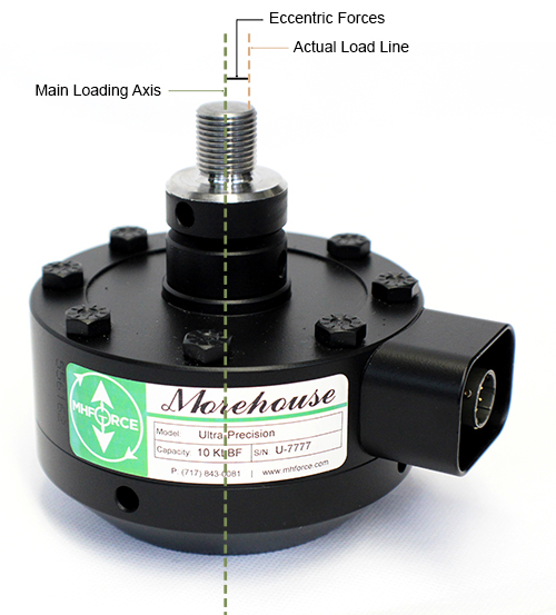
Figure 1 Example of Axial Application of Force
Resolution
As defined in section7.2
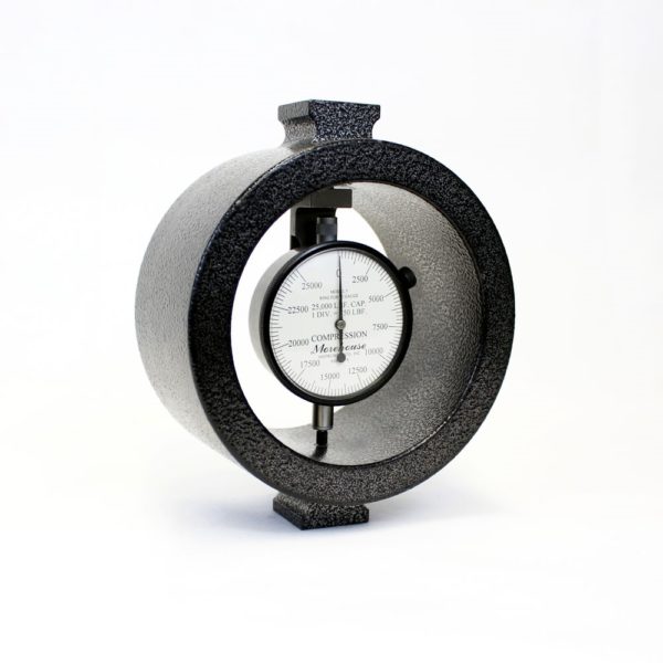
Figure 2 Example of an analogue scale on a Morehouse 25,000 lbf Ring Force Gauge
“Analogue Scale -The resolution, r, of the indicator, shall be obtained from the ratio between the width of the pointer and the centre-to-centre distance between two adjacent scale graduation marks (scale interval), the recommended ratios being 1:2, 1:5 or 1:10, a spacing of 1,25 mm or greater being required for the estimation of a tenth of the division on the scale.”
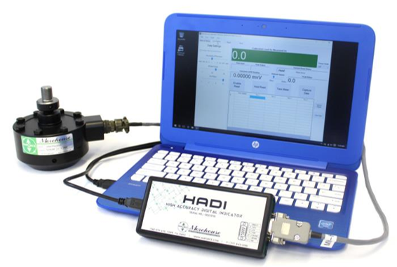
Figure 3 Example of a digital system reading by 0.1 force units
“Digital Scale - The resolution is considered to be one increment of the last active number on the numerical indicator. If the reading fluctuates with no force applied, the resolution will be the fluctuation divided by 2.”
Selection of Forces
ISO 376 requires at least 8 force points throughout the range, at least 4 runs of data, and a creep test if the force-measuring instrument is to be used for incremental loading only. However, if the force-proving instrument is to be used for both incremental and decremental loading, then two extra runs of data are taken, making the total of runs 6. ISO 376 does not allow the first test point to be less than 2 % of the measuring range and has classifications that specify that the first point cannot be less than 4000 times the resolution for Class 00, 2000 times the resolution for Class 0.5, 1000 times the resolution for Class 1, and 500 times the resolution for class 2.
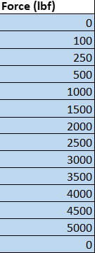
Figure 4 Selection of Forces based on Morehouse Recommendations
Morehouse typically recommends selecting between 12 calibration points as it will make classifying the instruments easier below 10 %. We usually select a point that is 4000 times the resolution or 2 % whichever is greater, and a 5 % point, and then try to choose a point around every 10 % through 100 %.
Creep Tests
ISO 376 requires a creep test if only incremental loads are applied. Per section 7.4.4 “If the force-proving instrument is to be calibrated in an incremental-only loading direction, record its output at 30 s and 300 s after application or removal of the maximum calibration force, in each mode of force application, to enable its creep characteristics to be determined. If creep is measured at zero force, the maximum calibration force shall be maintained for at least 60 s prior to its removal. The creep test may be performed at any time after preloading during the calibration procedure.”
Make sure to report on the certificate when and how the creep test was performed.
Time Requirements for Application of Forces
ISO 376 states in section 7.4.3, “The time interval between two successive loadings shall be as uniform as possible, and no reading shall be taken within 30 s of the start of the force change.”
Determination of Deflection
ISO 376 defines deflection as the difference between a reading under force and a reading without force.
Calibration Procedure
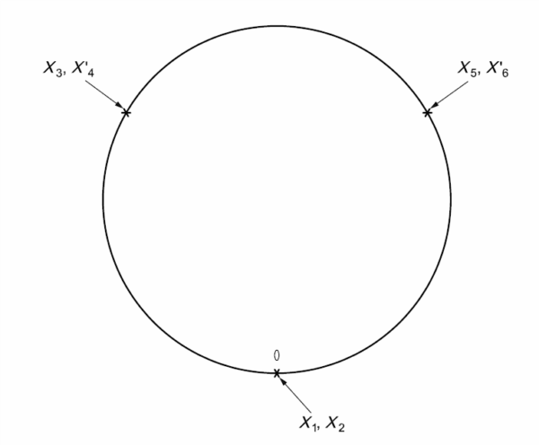
Figure 5 Diagram of the loading positions
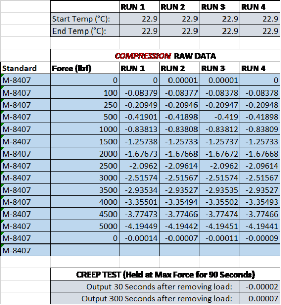
Figure 6 Example of calibration data for increasing forces only and creep test
- Allow the instrument to acclimate
- Turn on any electronics and warm up as needed (30 minutes is a good warm-up)
- Setup the force-proving instrument in the calibration frame
- After the force-proving instrument is set up in the machine section 7.4.1 requires the maximum force to be applied to the instrument three times and the duration of that application should be between 60 and 90 seconds.
- Carry out the calibration by applying two series of calibration forces to the force-proving instrument with increasing values only, without disturbing the device. 0-degree orientation X1 and X2. This data will be used to test for repeatability.
- Apply at least two further series of increasing (shown in Figure 6) and, if the force-proving instrument is to be calibrated in an incremental/decremental loading direction, decreasing values. Between each of the further series of forces, rotate the force-proving instrument symmetrically on its axis to positions uniformly distributed over 360° (i.e. 0°,120°, 240°). See Figure 5 for positioning. If this is not possible, it is permissible to adopt the following positions: 0°, 180°, and 360°
- Perform a creep test – This is the recommendation of Morehouse to perform a creep test if needed at the end of the calibration. ISO 376 allows a creep test to be performed at the beginning of the calibration after exercising or preloading the force-proving instrument.
- Run the data analysis. Note: ISO 376 allows the use of curves up to a 3rd-degree only. These are the polynomial curves that allow solving for force or solving for response and the polynomials are entered into the Morehouse software for our force systems to display all values in the appropriate engineering units ie N, Kn, gF, lbf, kgf, etc..,
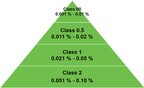
Figure 7 ISO 376 Expanded Uncertainty of Applied Calibration Force
Calculation and Analysis of Data
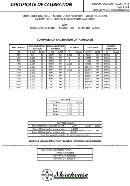
Figure 8 Example of data analysis and class assignments on a Morehouse 5K load cell
ISO 376 uses the observed values to ensure that certain characteristics of the force-proving instrument are met and rates the device's performance based on its characteristics. ISO 376 uses either four runs of data and a creep test or six runs of data to characterize the force-proving instrument and the associated relative error. ISO 376 then takes the highest error percentage per point for each parameter and assigns a class based on the highest error shown in Figure 9 below. Force-proving instruments where only increasing data is used (four runs of data) are tested for reproducibility, repeatability, resolution, interpolation, zero, and creep.
However, force-proving instruments where increasing and decreasing data are used (six runs of data) are tested for reproducibility, repeatability, resolution, interpolation, zero, and reversibility. The expanded uncertainty of the applied calibration force must also be less than the table allows. If a force-proving instrument has a relative error % for one of the parameters more than what is required for Class 00 but meets the criteria for all other parameters, then the best classification for the device is limited by class for the highest error. ISO 376 classifies everything per point and then breaks down the classification per loading range. If the relative error of reversibility is Class 1, but all other criteria meet Class 00, then the device is rated as a Class 1 device if the expanded uncertainty of the applied calibration force meets the criteria, as well. What ISO 376 does very well is that it accounts for the uncertainty of the applied calibration force within the standard. A force-proving device cannot have an Uncertainty of less than the reference used for calibration, as shown in Figure 7 above.
The ISO 376 standard goes into further detail about all the requirements for classifying the force proving-instrument in section 8 of the standard. Anyone wanting to know those exact requirements should purchase the ISO 376 standard and consider attending our ISO 376 Explained webinar.
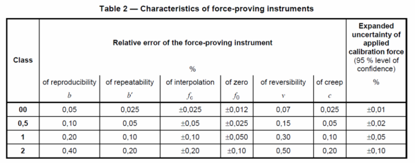
Figure 9 Table 2 from ISO 376 Standard for Classification of Force-Proving Instruments
Recalibration Dates
ISO 376 in section 8.3.2 allows for a maximum validity of the calibration certificate to not exceed 26 months.
Reporting Criteria
ISO 376 requires:
- the identity of all elements of the force-proving instrument and loading fittings and of the calibration machine;
- the mode of force application (tension/compression);
- that the instrument is in accordance with the requirements of preliminary tests;
- the class and the range (or forces) of validity and the loading direction (incremental-only or
- incremental/decremental);
- the date and results of the calibration and, when required, the interpolation equation;
- the temperature at which the calibration was performed;
- the uncertainty of the calibration results (one method of determining the uncertainty is given in Annex C);
- details of the creep measurement, if performed.
Annex
The ISO 376 appendix deals with bearing pad tests, which are highly recommended for verifying that there is no interaction between the force transducer of an instrument used in compression and its support on the calibration machine. Morehouse can perform bearing pad tests if requested. ISO Annex A 4 discusses loading fittings. Loading fittings should be designed in such a way that the line of force application is not distorted. As a rule, tensile force transducers (shown in Figure 10 below) should be fitted with two ball nuts, two ball cups, and, if necessary, with two intermediate rings, while compressive force transducers should be fitted with one or two compression pads (shown in figure 11 below).
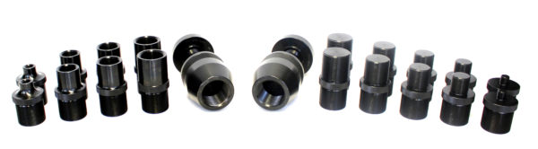
Figure 10 Morehouse Quick Change Tension Adapter Value Kit meets ISO 376 standard annex A.4 requirements.
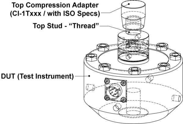
Figure 11 Drawing of Morehouse Load Cell with ISO 376 Compression Adapter
Summary
ISO 376 does a very thorough job of classifying the device and providing the end-user with an expected performance of the force-proving instrument. If the end user chooses to implement the proper adapters to ensure proper alignment and replicate the stress distribution, then they should expect to be able to replicate the calibration results on whatever they are calibrating. The standard addresses adapters, and bearing pad tests and provides a great deal of guidance. The uncertainty of the reference standard used to perform the calibration helps determine the class assignments.
ISO 376 goes into detail on how to calculate the expanded uncertainty and ensures those following the standard will propagate uncertainty correctly. The uncertainty contributors are shown in Figure 11. If you need calibration in accordance with the ISO 376 standard and expanded uncertainty reported correctly, it is important to look at the scope of accreditation of your calibration supplier and verify that your calibration provider has the capability mentioned on their scope, as shown in Figure 12. Anyone wanting to know more about ISO 376 should purchase the standard on the ISO website here.
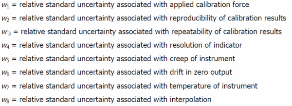
Figure 12 Requirements for uncertainty calculation
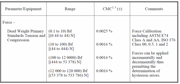
Figure 13 Sample from Morehouse Scope Showing ASTM and ISO 376 Capability
References
ISO 376:2011 Metallic materials — Calibration of force-proving instruments used for the verification of uniaxial testing machines.
If you enjoyed this article, check out our LinkedIn and YouTube channel for more helpful posts and videos.
About Morehouse
Everything we do, we believe in changing how people think about force calibration. Morehouse believes in thinking differently about force and torque calibration and equipment. We challenge the "just calibrate it" mentality by educating our customers on what matters, and what causes significant errors, and focus on reducing them.
Morehouse makes our products simple to use and user-friendly. And we happen to make great force equipment and provide unparalleled calibration services in accordance with customer requirements, ASTM E74, ASTM E2428, and ISO 376.
Wanna do business with a company that focuses on what matters most? Contact Morehouse at info@mhforce.com

