

The Pros and Cons of Load Cell Simulator Calibration: Is Interchangeability Worth It?
We have been asked more frequently about the benefits of calibrating everything as a system versus calibrating the load cells and indicators separately and intermixing them using a calibrated load cell simulator.
Being able to intermix any load cell and meter combination makes a lot of sense.
If someone needs two load cells and a meter to do a specific job, they can check out the two load cells and a meter and adapters and perform the calibration or test.
The other unused load cells would then be available for someone else. If done correctly, this would be quite beneficial.
However, many disadvantages and obstacles remain, such as maintaining(calibrating) a load cell simulator with enough span points, establishing metrological traceability, and correctly calculating its measurement uncertainty.
Every meter needs calibration, contributing to a larger overall measurement uncertainty.
As you now do not have a married system, you need to independently establish traceability for both the load cell and meters.
Let's start by dealing with ISO 376 and ASTM E74 standards requirements.
These are standards required for calibrating force-proving instruments, most commonly known as load cells, to calibrate other force-measuring instruments, force machines, hardness machines, and testing machines, using ASTM E74, ASTM E4, ASTM E-10, ASTM E-18, ISO 376, ISO 7500 and so on.
ISO 376 and ASTM E74 requirements for meter calibration
ISO 376 in section C.2.11 Effect of a replacement indicator states,
"The deviation between the two indicators should be determined (there are several methods, e.g., calibration of both indicators, use of a common bridge simulator), and the uncertainty of this deviation should be estimated (including factors such as the calibration uncertainty of the indicators and the stability of the common bridge simulator).
If corrections are made, the uncertainty of the deviation should be taken into account. If no corrections are made, the deviation and its uncertainty should be considered."
Section 5 of the standard goes into more detail about when an electrical measurement is made. It goes on to list conditions that must be fulfilled, such as:
- The calibration of the indicator shall be traceable to national standards, and the replacement indicator shall be calibrated over a range equal to or greater than the range for which it is used with the force-proving instrument, and the resolution of the replacement indicator shall be at least equal to the resolution of the original indicator when it is used with the force-proving instrument.
- The units shall be of the same quantity: 5V, 10V, AC, or DC.
- It is recommended that the replacement indicator be no greater than 1/3 of the uncertainty of the entire system.
Additionally, ISO 376 mentions programming indicators using span points.
If one does not use the calibration equation and programs point into an indicator that allows points from the calibration curve to be input so that the display is in units of force or torque but carries out linear interpolation between these points, the effect of this approximation to the curve should be investigated, and an uncertainty contribution should be included.
ISO 376 section 3.1 defines a force-proving instrument as a "whole assembly from the force transducer through to, and including, the indicator."
One might be thinking, I do not calibrate following ISO 376. Maybe one only uses the ASTM E74 standard or a commercial calibration.
ASTM E74 is very similar in the requirements for substitution.
Section 12 is explicitly titled Substitution of Electronic Indicating Instruments Used with Force-Measuring Systems.
The standard acknowledges that it might be desirable to treat the indicator and force-measuring instrument separately.
A huge benefit is that if you purchase the same indicators, one could be used as a backup if the primary unit fails.
Potentially, the expensive calibration of the entire system could be avoided.
Then, the standard lists conditions that shall be satisfied to substitute a metrologically significant element of the electronic indicating instrument.
ASTM E74 Section 12.1.1 specifically states, "The electronic-indicating instrument used in the initial calibration and the instrument to be substituted shall each have been calibrated and their measurement uncertainties determined. The electronic indicating instrument to be substituted shall be calibrated with traceability to the SI over the full range of its intended use including both positive and negative values if the system is used in tension and compression.
The calibrated range shall include a point less than or equal to the output of the force transducer at the lower force limit and a point equal to or greater than the output of the force transducer at the maximum applied force. A minimum of five points shall be taken within this range. The measurement uncertainty of each electronic indicating instrument shall be less than or equal to one-third of the uncertainty for the force-measuring system over the range from the lower force limit to the maximum force."
The section then states, "12.1.3 Excitation voltage amplitude, frequency, and waveform shall be maintained in the substitution within limits to ensure that the effect on the calibration is negligible. It is a user responsibility to determine limits on these parameters through measurement uncertainty analysis and appropriate tests to ensure that this requirement is met."
To summarize, you must calibrate a simulator to comply with the standard. The simulator must be capable of positive and negative values if the load cells are used in both positive and negative directions. The simulator must have at least one point less than or equal to the lowest force point value in the range and one for the highest point.
Below is a picture of a Morehouse simulator. This simulator likely cannot be used to satisfy these requirements.
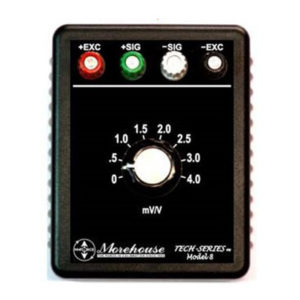
The first point is 0.5 mV/V, and the last one is 4 mV/V. If someone had a 4 mV/V (10,000 Force Units) load cell and the verified range of force was 500 through 10,000 Force Units, the simulator at 0.5 mV/V would be 1,250 Force Units. If the verified range of forces started at 200, a 0.08 mV/V first step would be required.
Note: The best high-end simulators typically have the first step of 0.04 mV/V or lower, as 0.04 mV/V on a 2 mV/V load cell equates to a 2 % llf. A simulator that starts at 0.1 mV/V would equate to a 5 % llf on a 2 mV/V load cell.
2 mV/V is 5,000 Force Units. The end-user would need to raise their Class A verified range of forces to 1,250 FU using this simulator. This situation does not work for many, as they want to capture force values from the first non-zero calibrated point, typically below 5 % of the load cell's capacity.
The ASTM E 74 standard provides further guidance by stating that the indicator's measurement uncertainty shall be determined by one of the methods in Appendix X2. The appendix is non-mandatory, and there are likely other ways to establish a traceability path. However, section 12 is mandatory, and the end-user must abide by it.
In no case can someone substitute a meter without meeting the measurement uncertainty and traceability requirements.
The standard further recommends that the simulator have a series of mV/V steps of the measurement range with similar impedance characteristics and states this requirement in section 12.1.2; thus, this criteria needs to be adhered to.
"The measurement uncertainty of the transducer simulator shall be less than or equal to one-tenth of the uncertainty for the force-measuring instrument." ASTM E74 further states, "Excitation voltage amplitude, frequency, and waveform shall be maintained in the substitution within limits to ensure that the effect on the calibration is negligible.
It is a user's responsibility to determine limits on these parameters through measurement uncertainty analysis and appropriate tests to ensure that this requirement is met. Substitution of an interconnect cable can have a significant effect on calibration. If an interconnect cable is to be substituted, see Note 15."
- This is interesting as the interconnect cable for the simulator does not always share the same connection as the load cell. If the system is not 6-wire, meticulous care will need to be made to ensure the same gauge wire and length is used for the simulator to meter connection as that of the load cell. Note 15 goes into more detail, and Morehouse has an article explaining why 4-wire systems are not ideal. That article can be found here.
Appendix X2 details steps necessary to start to determine the uncertainty and recommendations for calibrating the meter for substitution. Morehouse fully supports ASTM E74 and feels the membership is incredible. For around $100.00, one can join and get access to a catalog of standards. This author's opinion is that this is one of the best deals in the industry. Signing up is simply at astm.org. The E-28 committee is responsible for standards such as ASTM E74, ASTM E2428, ASTM E10, ASTM E18, and ASTM E4.
Summary of Top Requirements for Load Cell Simulator Calibration Needed for Meter Substitution
The summation of what is needed is as follows:
- At least five readings for each polarity over the range must be taken.
- The points need to be less than or equal to the first point in the Class A or AA verified range of forces, and the capacity needs to have a point equal to or greater than the maximum output observed during calibration. So, if loading a 10,000 Force Unit load cell to 11,000 Force Units, which might read 4.4 mV/V, a 4.0 mV/V simulator is not good enough.
- The load cell simulator shall provide at least one point for every 20 % interval throughout the range. (Interesting tidbit here as the standard says five points, though the simulator likely needs to have the low force point and an additional 5 points to cover up to capacity or higher for a total of six points throughout the range)
- Section 8. Calculation and Analysis of Data of the ASTM E74 standard provides guidance to determine the standard deviation Type A uncertainty component for calibration of the indicator.
- The excitation voltage, waveform, and other characteristics need to be maintained.
Okay, so the benefits might still outweigh the additional headache of using a simulator and being able to separate one's load cells from the indicator or decouple the system.
However, there are a lot more error sources one needs to be aware of.
One of the error sources we see missed quite a bit is not having the load cell calibration excitation and waveform match that of the meter being used. A good example is many USB digital indicators providing less than 10 V DC output. To comply with these requirements, one must have their load cells calibrated at the same excitation and waveform as the meter. If the USB meter puts out 5 VDC, then the load cell calibration should be at 5 VDC.
Additional error sources include Calibration Uncertainty (Gain Error), Zero Offset, Temperature Effect on Sensitivity, Quantization Error, Normal Mode Voltage, Power Line Voltage Variation, Non-Linearity, Temperature Effect on Zero, Gain and Zero Stability, Common-Mode Voltage, Noise, Electrical Loading, Error Signals due to thermal EMF, Difference in cabling if not a true 6-wire system. All these error sources should be evaluated.
When the amount of work required to capture all of these error sources, dot all of the I's and cross all of the T's is considered, we often find it much more sensible to consider buying one digital indicator per load cell. Most of these USB-type digital indicators, like the Morehouse HADI, are excellent, very reasonably priced, and can easily accommodate the goal of scheduling equipment.
If a load cell or a meter malfunctions, only one piece of equipment is down, and work can likely continue.
Morehouse can work with anyone to get that equipment back up quickly. If a HADI indicator gets run over, dropped, or damaged, we could replace and calibrate the load cell with the new meter as a system quickly—in less than two weeks.
I believe marrying one indicator to a load cell is often less risky and more cost-effective. It provides all the benefits of using different-size load cells for various measurements. Going down the substitution route requires separate calibration for the load cell and each indicator.
The long-term cost is typically much larger, as is the overall measurement uncertainty.
You are effectively now paying for two calibrations instead of one system calibration.
Typical Error Sources for Meter Substitution
When calculating Measurement Uncertainty for a meter to be used for substitution, the following are typical error sources:
Simulator Uncertainty includes the resolution of the meter, simulator calibration and the associated reference standard uncertainties, stability of the simulator, and ratio uncertainty. At Morehouse, we achieve about ± 0.00005 mV/V uncertainty on our high-end simulator using different cables for positive and negative output as the polarity switch introduces additional uncertainty.
On the meter side, Non-linearity, Stability, Environmental, Ref Uncertainty from the Simulator, Additional Cable Uncertainties, Noise or Resolution, Repeatability, and Reproducibility.
In our experience, most who use meter substitution add about 0.02 %—0.04 % uncertainty to their systems. This is too much uncertainty for ASTM Class AA calibrations, which are expected to be better than 0.05 %, too much for ISO 376 Class 00, 0.5, and likely too much for Class 1 & 2. The requirement for an ASTM Class A is to be better than 0.25 %. The contribution to uncertainty is often significant, though somewhat manageable.
I have discussed this topic with NIST and was told that they do not assign a Class A or AA-verified range of forces when calibrating load cells sent in without an indicator. This is an interesting debate for those calibrating following ASTM E74, as the LLF should be different when substituting meters, as the additional uncertainty would impact the verified range of forces.
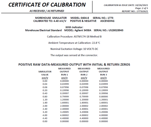
Morehouse does offer calibration of load cell simulators to comply with either standard. Below is a page from our calibration report for one of our reference load cell simulators. The load cell simulator was explicitly designed to calibrate meters.
These simulators have high-quality aged resistors and steps from 0.04 – 4.4 mV/V. The standard deviation is less than the resolution, hence the importance of having the resolution as part of the overall measurement uncertainty.
We have written a technical paper on the importance of instrument resolution in an uncertainty budget. That paper can be found here.
Morehouse Budget Load Cell Simulator
Back to the simulator, it is likely not good enough to calibrate the meters for substitution. Why would anyone want this? The best answer is cost. The simulator is under $600.00 compared with a higher-end model that costs over $4,500.00 plus calibration. So, what? It does not allow me to calibrate my meter. That is technically correct, though it is a very powerful tool.
Our simulator allows the end user to do the following:
- Perform cross-checks on equipment
- Help control stability/drift
- Verify coefficients are correctly entered in our 4215 plus, C705P meter; both use the actual coefficients from the calibration report. Verify coefficients for other programs, such as Morehouse calibration software.
- Check for linearity issues in any meter.
- Use as a diagnostic tool to rule out the load cell meter, leaving the load cell, cables, or adapters as the issue.
- It can be used to calibrate A/D offset and gain settings.
- It can be used to set up a new indicator before system calibration.
Load cell Simulator - Conclusion
If you want to read more, please purchase the ISO 376 and ASTM E74 standards. If you are performing meter substitution, you should have controlled copies of any standard you are trying to comply with.
When accessing overall measurement uncertainty, I always strive to do what yields the lowest overall measurement uncertainty to limit the overall risk. Calibrating everything as a system is much better, keeping the measurement traceability chain clean.
Adding a load cell simulator and its associated measurement uncertainty and the calibration of several meters can be challenging.
Many people struggle with calculating measurement uncertainty for "married" systems, and adding more requirements creates additional uncertainty and headaches.
There is a risk/reward scenario for separately calibrating the indicator and load cells. Much additional work is required to comply with either ISO 376 or the ASTM E74 standard. It might be worth it if that extra work saves time and money.
Any meter used for substitution must have the same characteristics, excitation, and waveform.
Plus, the overall uncertainty increases by an additional 0.02 – 0.04 %, which will be absorbed by everyone else down the metrological traceability pyramid.
Though not suitable for meter calibration following ISO 376 or ASTM E74, our budget simulator can save a lot of time when troubleshooting equipment and verifying everything was keyed incorrectly via coefficients from a calibration report without breaking the bank.
We can provide higher-end simulators for indicator substitution, though the cost is likely over $5000.00, depending on the exact steps and requirements.
If you enjoyed this article, check out our LinkedIn and YouTube channel for more helpful posts and videos.
At Morehouse, we educate our customers to comply with the published requirements from both ASTM E74 and ISO 376 regarding load cell simulator calibration and meter substitution.
We have been in business for over a century and focus on being the most recognized name in the force business. That vision comes from educating our customers on what matters most and having the proper discussions about force calibration concepts so everyone uses the proper methods.
We believe in changing how people think about force and torque calibration in everything we do. We challenge the "just calibrate it" mentality by educating our customers on what matters and what causes significant errors and focusing on reducing them.
In addition, Morehouse makes simple-to-use calibration products. We build excellent force equipment that is plumb, level, square, and rigid. We provide unparalleled calibration service with less than two-week lead times.
Contact us at 717-843-0081 to speak to a live person or email info@mhforce.com for more information.
#Simulator Calibration #Load Cell Simulator Calibration # Load Cell Simulator

