

Cosine Error Should be Considered in any Torque Measurement Process
ISO/IEC 17025 When Calculating Torque Measurement Error Cosine Error should be considered
A ‘vector’ is known as a quantity that is defined by its size and direction. Every time the effect of a known force is evaluated on a static or dynamic system, all applied, and resulting forces should be determined by both their magnitude and direction. For instance, if one says that a 100 lbf force is applied at ‘point X’ on a table, without fully defining the applied force direction, an infinite number of solutions each with its own set of results can be generated.
One method of measuring torque is by applying a known force to the end of an arm with a known length. One end of the arm is normally fixed to the point of interest where the torque is measured, and the known force is applied to the other end of the arm. The applied torque is then determined by multiplying the applied force by the torque arm length. If done correctly, this simple method can be the most accurate method of torque measurement.
Most high-accuracy torque measurements by National Metrology Institutes such as PTB and also by Morehouse are done by this method. Numerous details must be considered in the setup of such torque measurement machines, and they are typically made to the highest manufacturing precision standards available. The known force in these machines is induced by deadweights accurately calibrated and adjusted for local gravity, material density, and other factors that may affect the gravitational forces applied to a known mass. In deadweight torque machines, the system allows the gravity forces to align the applied force; however, the fixed point where the torque transducer is installed is precisely manufactured and maintained during calibration to produce a 90° angle between the applied force and torque arm direction. In other words, the force vector in the machine is defined by the number of deadweights (calibrated for force) and gravity direction.
For general industrial purposes, however, some accuracy might be sacrificed for faster and more efficient torque measurements. When accurately calibrated torque wrenches are not available, some users may try to use alternative methods such as the one shown in Figure 1 to measure torque. Although this method might look feasible at first glance, it is very difficult to maintain all requirements of a proper torque measurement with it. One potential issue could be the determination of applied force assuming the device was calibrated using force and not mass weights as discussed in our previous post.
If we assume the dynamometer used in Figure 1 shows the applied force with 100% accuracy (which does not exist in real life), still without knowing the complete characteristics of the force vector, this method could lead to highly erroneous torque measurement values. By having a second look at Figure 2, you will realize that the angle between the wrench direction and the applied force is not close to 90°. Only this one factor can result in major errors in the measured torque value if it is not accounted for.
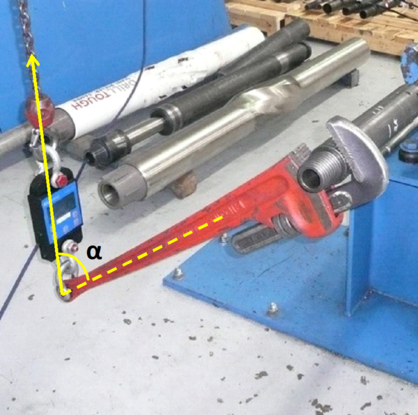
Figure 1: High potential error in torque measurement by using a pipe wrench and a dynamometer
The effect of a known vector can be evaluated and expressed in various directions by calculating its representation in those directions. Different methods might be used for various coordinate systems such as Cartesian, polar, cylindrical, and spherical. In the most simplistic form, the applied force vector can be expressed in a two-dimensional flat plate, in X and Y directions. With this method, the user can determine the actual torque-generating force applied to the pipe wrench shown in Figure 1. In this example, if we assume the applied force is 150 lbf, and the length of the wrench (from the pipe center to the force application) is exactly 2 ft, the user might simply conclude that the applied torque is:
150 lbf x 2 ft = 300 lbf.ft
The above calculation can be true if the applied force angle a is equal to 90° and the force application plane is perfectly perpendicular to the pipe direction. However, if we assume a=40° as shown in Figure 2, only a portion of the 150-lbf force generates torsion at the center of the pipe, and the rest of it is spent on pushing the pipe upward parallel to the wrench direction. Figure 2 better demonstrates this concept. To find the actual torque-generating force on the wrench, the applied force should be expressed in the X and Y directions; parallel to the wrench and perpendicular to the wrench respectively. The diagram in Figure 2 demonstrates the methodology of this expression. Using this method, the torque-generating force (FY) will be:
FY = F . Sin(a) = 150 x Sin(40°) = 96.42 lbf
And the force applied parallel to the wrench handle:
FX = F . Cos(a) = 150 x Cos(40°) = 114.91 lbf
The generated torque at the center of the pipe will be:
T= FY . L = 96.42 x 2 = 192.84 lbf.ft
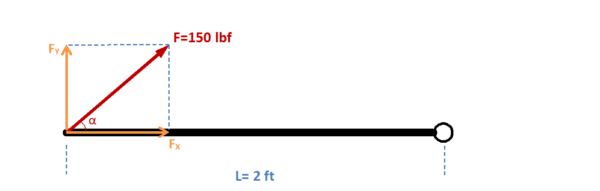
Figure 2: Expression of the applied force F in X and Y directions
As this simple example demonstrates, neglecting the effect of the applied force angle can make a 192.84 lbf.ft applied torque look like a 300 lbf.ft; in other words, 36% error. In addition, the angle of the applied force induces the FX force component parallel to the wrench handle. The wrench directly transfers this extra force to the torque-measurement point. If there was a torque sensor used here in place of the pipe, extra errors would have been realized from the lateral forces to the torque sensor. In summary, it might be true that torque equals force times distance. However, there are many details that need to be considered and taken into account to determine the right force, distance, uncertainties, and parasitic errors during measurements such as friction, misalignment, temperature, later loads, etc.
If you enjoyed this article, check out our LinkedIn and YouTube channel for more helpful posts and videos.
Everything we do, we believe in changing how people think about force and torque calibration. Morehouse believes in thinking differently about force and torque calibration and equipment. We challenge the "just calibrate it" mentality by educating our customers on what matters, and what causes significant errors, and focus on reducing them.
Morehouse makes our products simple to use and user-friendly. And we happen to make great force equipment and provide unparalleled calibration services.
Wanna do business with a company that focuses on what matters most? Email us at info@mhforce.com

