

Guidance on Uncertainty Budgets for Force Measuring Devices Part 1. Why Do We Need a Solid Guidance Document?
Uncertainty Budgets for Force Measuring Devices Introduction: All calibration laboratories accredited to ISO/IEC 17025 must submit uncertainty calculations for the Calibration and Measurement Capability uncertainty claims included in the scope of accreditation. The assumptions made to determine the uncertainty budgets, if any, must be specified and documented. Any accredited and enrolled calibration laboratories shall calculate measurement uncertainties using the method detailed in the ISO “Guide to the Expression of Uncertainty in Measurement” (GUM)1
Purpose:
These blogs provide guidance for determining the proper contributors of parameters for force measuring devices that should be considered when developing uncertainty calculations that support Calibration and Measurement Capability (CMC) uncertainty claims made on a scope of accreditation.
This guidance document also serves as a means for labs to comply with section 6.8 of A2LA R205 – Specific Requirements and other accreditation bodies' requirements. Calibration Laboratory Accreditation Program. Finally, for instruments that are calibrated in accordance with ASTM E74 or ISO 376, it goes beyond R205 to include sections in ASTM E74 and ISO 376 that should be considered for determining a lab's Calibration and Measurement Capability (CMC).

Background:
There are vast discrepancies between auditors regarding what is acceptable for a force calibration uncertainty budget. One auditor will say do it this way, another one may understand force and assess the lab properly, and the third auditor may just ask for repeatability and not even know the parameter they are assessing well. It is almost as if you have three directions you can go, and only one in three auditors will get you to that destination.
One of these issues involves how to calculate uncertainty correctly when the lab is following a standard like ASTM E74 or ISO 376. If calibrating to ASTM E74 or ISO 376 standards, then contributions from Non-Linearity, Static Error Band, or Hysteresis should not be considered for the uncertainty budget and replaced by the ASTM LLF (Lower Limit Factor).
Another common mistake is to include too many lines from the load cell specification sheet. For example, if a load cell is used to make ascending measurements only, the effect of the uncertainty contribution for hysteresis should not be included in the uncertainty budget. Not understanding the load cell specification sheet is another error source.
When the specification sheet says units of RO, this is a percentage of the Rated Output of the load cell. The percentage of RO is linear throughout the range, meaning 0.02 % of Rated Output at the instrument's capacity is 0.2 % at 10 % of the range. This document will provide four examples that should account for most instrumentation used for force measurements.
General Guidance:
Force-measuring devices generally fall into two categories.
- Force-measuring devices for calibration of other force-measuring equipment
Note Any calibration laboratory performing calibration to further disseminate the unit of force would fall into this category.
- Force-measuring devices for measurement of force.
Note: The end user of a force measuring device used for an application where there is a “go/ no-go” or “Pass/Fail” scenario where the testing stops, and there is no further dissemination of force.
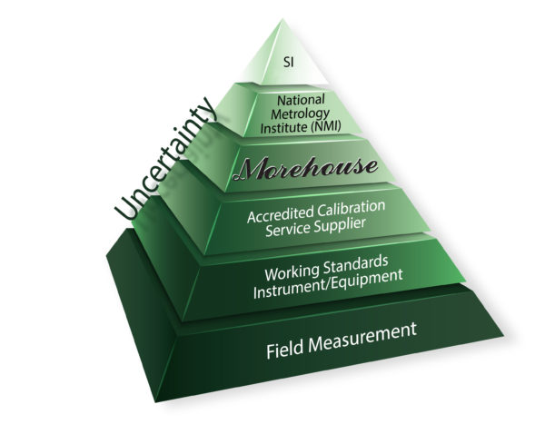
Calibration Traceability and Uncertainties
All force measurements are traceable to SI Units of time, length, and mass. The progression of traceability for force is primary deadweight standards which generally have the lowest uncertainties between 0.001 % to 0.005 % of the applied force.
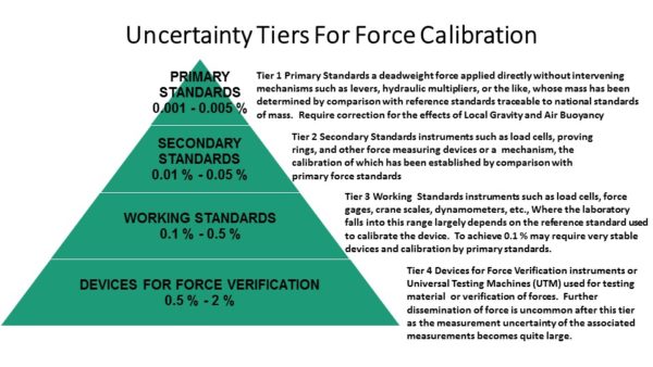
Primary Standards are required to calibrate Secondary Standards such as load cells, proving rings, and other force-measuring devices. The uncertainties at this level are generally between 0.01 % to 0.05 % of the applied force. To achieve less than 0.025 % is extremely difficult and calls for the utmost control of environmental, adapters, and other loading conditions. Most labs will fall between 0.03 % to 0.05 % of the applied force.
Either Primary or Secondary Standards can be used to calibrate force-measuring devices referred to as working standards. The working standards can be force measuring devices such as load cells, force gages, crane scales, dynamometers, etc., Working standards typically have uncertainties of 0.1 % through 0.5 % of the applied force.
Where the laboratory falls into this range largely depends on the reference standard used to calibrate the device as well as calibration equipment, adapters, and environmental conditions. To achieve 0.1 % may require very stable devices and calibration by primary standards.
Devices for Force Verification – These devices typically have uncertainties of 0.5 % or higher. They are used to verify the force applied. The most common example would be a force testing machine where material samples are tested with an uncertainty of 1 %.
Note: Secondary standards cannot be used to calibrate other secondary standards, and working standards cannot be used to calibrate other working standards. The devices calibrated by working standards cannot be used to further disseminate the unit of force for calibration purposes.
Picture from A2LA June 2009 Newsletter. Gives a nice summary of Uncertainty Contributors.
Guidelines for calculating CMC
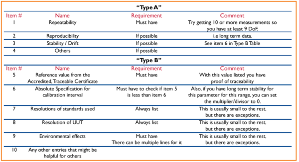
Type A Uncertainty, Contributors
The GUM states that all statistical data is treated as Type A contributors with normal distributions. Typical examples in these areas are:
1) Repeatability
2) Reproducibility
3) Stability / Drift *
4) others (This would include ASTM E74 LLF, ISO 376 Uncertainty, Non-Linearity, or SEB)
* Repeatability is required by the GUM and M3003. Note: For our examples, stability will be treated as type B because we are taking values over a range using previous measurement data.
Type B uncertainty contributors
Per section 4.3 of the GUM Type B evaluation of standard uncertainty may include:
- previous measurement data;
- Experience with or general knowledge of the behavior and properties of relevant materials and instruments;
- manufacturer’s specifications;
- data provided in calibration and other certificates;
- uncertainties assigned to reference data taken from handbooks.
A2LA R205 clarifies these type B contributors by requiring:
- Resolution of the Reference Standard
- Resolution of The Best Existing Device or Device used for Repeatability Studies
- Reference Standard Uncertainty
- Reference Standard Stability
- Environmental Factors
- Other Error Sources
Other Error Sources – When evaluating other error sources, it is important that the end user of the device replicates how the device was calibrated or that the laboratory performing the calibration is replicated how the instrument is being used. Fixturing and adapters used with the force-measuring device may have a significant contribution to the overall uncertainty of the force-measuring device.
Note: For the parameter of force, some labs have top-quality force machines such as deadweight machines. These machines are classified as primary standards and if designed correctly some of the above error sources can be found to be insignificant. If an assessment of A2LA document R205 is required, these error sources will need to be accounted for. Repeatability of a top-quality device in a deadweight machine (Several labs using primary standards have found this to be less than 2 ppm).
The resolution of a top-quality device can be better than 1 ppm if high-quality indicators reading six decimal places or more are used. It is also common to find reproducibility and repeatability between technicians to be insignificant. It is important to note that these three error sources may be found to be insignificant using deadweight primary standards, often becoming significant at the next measurement tier.
Common error sources for force include:
- Alignment
- Using a different hardness of adapter that was used for calibration
- Using different size adapters than what was used for calibration
- Loading against the threads instead of the shoulder
- Loading through the bottom threads in compression
- Temperature effects on non-compensated force measuring devices
- Cable length errors on a four-wire system
- Using Electronic Instruments (Indicators) that were not used during calibration
- Using an excitation voltage that is different from the voltage used at the time of calibration
- Variations in bolting a load cell to a base for calibration while the application is different
- Not replicating via calibration how the equipment is being used
- Failure to exercise the force measuring device to the capacity it was calibrated prior to use.
The next series of Blogs will deal with Specific Guidance on Calculating CMCs
Specific Guidance
Force Measuring Devices for Calibration of Other Force Measuring Equipment
- a)Devices calibrated in accordance with the ASTM E74 Standard
- b)Devices not calibrated to any known standard
- c)Force Measuring Devices for Measurement or Verification of Force
- d)Devices calibrated in Accordance with ISO 376
Note: It is highly recommended that all force-measuring devices for calibration of other force-measuring equipment be calibrated in accordance with the ASTM E74 standard or a comparable standard. There are several other published standards for force measurements followed in other regions. European nations typically follow ISO 376. The ISO 376 standard annex C includes uncertainty contributors for the following: calibration force, repeatability, reproducibility, resolution, creep, zero drift, reversibility, temperature, and interpolation.
The intent of this Guidance Document is to address specific guidelines for force devices in North America where ASTM standards are predominately followed. Laboratories following the ISO 376 standard should follow the guidelines set forth in Annex C as well as the requirements of ILAC P-14 and ISO/IEC 17025.
We hope you continue to follow our posts. If anyone wants to review a full copy of our guidance document before it is published, please email hzumbrun@mhforce.com.
If you enjoyed this article, check out our LinkedIn and YouTube channel for more helpful posts and videos.
Everything we do, we believe in changing how people think about force and torque calibration. Morehouse believes in thinking differently about force and torque calibration and equipment. We challenge the "just calibrate it" mentality by educating our customers on what matters and what causes significant errors, and focus on reducing them.
Morehouse makes our products simple to use and user-friendly. And we happen to make great force equipment and provide unparalleled calibration services.
Wanna do business with a company that focuses on what matters most? Email us at info@mhforce.com.

