How to Calculate the Uncertainty of a Deadweight Primary Standard Machine

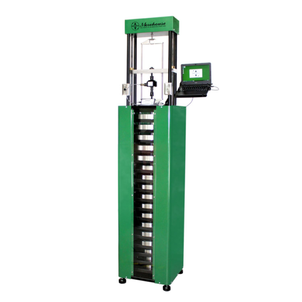
Figure 1: Morehouse 1,000 lbf automated deadweight machine
Deadweight Force Machines or Primary Force Standard (CMCs as low as 0.001 % of applied force) – a deadweight force applied directly without intervening mechanisms such as levers, hydraulic multipliers, or the like, whose mass has been determined by comparison with reference standards traceable to the International System of Units (SI) of mass. (Section 3.1.2 of ASTM E74-18) The weights are corrected for the effects of local gravity where the machine is to be used, air buoyancy, and material density.
The equation to adjust weights for force is as follows:
Force = M x g / 9.80665 m/s2 (1 – d/ D)
Where M = mass of weight, g = gravity at a fixed location, d = air density, and D = material density
Deadweight Primary Standard Machines are the most accurate method for calibrating load cells. When the overall accuracy of the load cell matters, it is highly recommended that calibration be performed by deadweight standards.
The Expanded Uncertainty of the Deadweight Primary Standard machine is typically broken down to two main components. One will be the Uncertainty of the individual weights, the other will be the uncertainty of several weights when applied together in the deadweight machine to achieve a certain test point.
The uncertainty of each weight in the machine shall be calculated as follows:
Each Weight will be assigned a target mass value and a calibrated mass. We would urge anyone to have the weights calibrated in Apparent or True Mass. Conventional Mass creates its own set of problems with monitoring barometric pressure.
When the reference lab calibrates the weights, they will report the actual value of the weight that they have adjusted it to. This value is the Calibrated Value. The difference between the Target Value and the Calibrated Value shall be reported as the Bias which is the difference from the nominal value.

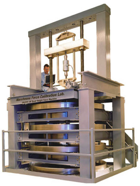
Figure 2: Morehouse 120,000 lbf reference lab standard deadweight machine known to be within 0.0016 %
Let’s look at an example using one of Morehouse’s 8000 lbf that is part of our 120,000 lbf machine.
An 8000 lb weight with a Target Value of 8005.707135 (adjusted for local gravity and air buoyancy using the equation above) and a Mass Value of 8005.716 lb determined at NIST.
The Bias = Target Mass – NIST Adjusted Mass, or 8005.707135 – 8005.716 = 0.008864642 lbs
Ref Unc = It is highly recommended that an ISO/IEC 17025 accredited laboratory such as Heusser Neweigh, Troemner, or if the budget allows NIST. The accredited laboratory will provide a calibration certificate for each weight which will include the target value, the calibrated mass value, and the uncertainty of their measurement or Reference Laboratory Uncertainty. In this example, the Reference Laboratory (NIST) Uncertainty is 0.0175 lbs Type A and B with a Normal Distribution
Material Density Unc = the uncertainty caused by the Material Density Determination. In our experience in using an accredited laboratory for material density determination, we can expect the uncertainty to be about 0.4 ppm. If we convert this number to lbs we take the Calibrated mass value 8005.716 x 0.4 ppm, we get 0.32022 lbs. We would urge AFPSL to verify that all bidders will be using an accredited laboratory for the calculation of Material Density and not handbook values. Type A and B with a Normal Distribution
Gravity Determination Unc = The uncertainty caused by gravity determination (if done on-site) is typically less than 1 ppm. When we had gravity determined the uncertainty of the determination was 0.960 ppm if we take 8005.716 x 0.960 ppm, we get 0.007685479 lbs If gravity is not done on-site the local value for the acceleration due to gravity, calculated within 0.0001 m/s2, may be obtained from the National Geodetic Information Center, National Ocean and Atmospheric Administration (NOAA). Type AB with a Normal Distribution
Air Density Unc = From ASTM E74-18 appendix section X1.3.1.4 “Buoyant forces equal to the weight of the air displaced is exerted on the weights. This force varies with atmospheric pressure and humidity. The correction factor is (1- d / D) where d = air density and D = weight density. The air density equation can be found in NIST Special Publication 700-1.” Then section 1.3.1.5 states, “Air density varies with fluctuations in barometric pressure, humidity, and temperature. According to NBS Monograph 133(7) at a constant temperature of 23 °C, changes in barometric pressure and humidity may cause the actual air density to vary as much as 3 % in either direction from the average air density at a given time and place.
Where the masses are maintained in an environment at 23 °C +/- 2 °C the variation in air density will cause a change in mass of the weight of 5.47 ppm (0.000547 %). This is a Type B uncertainty and is treated as having a rectangular probability distribution”. Morehouse has typically been conservative in this number as we based the determination on worst-case historical numbers and maintaining +/- 1.2 degrees C and not +/- 2 degrees. The uncertainty of the determination for Morehouse in our lab is 3.891 ppm if we take 8005.716 x 3.891 ppm, we get 0.031150206 lbs Type B with Rectangular Distribution.
Note: Most often the Air Density Unc includes contributions from temperature and humidity. Some labs may choose to continually monitor the temperature and humidity which may allow them to lower the uncertainty contribution.
Stability of the Weights Unc = From previous estimates and conversations with NIST the stability of each weight is 0.2 ppm. If we take 8005.716 x 0.2 ppm, we get 0.00160114 lbs. Studies performed on masses made from austenitic stainless-steel alloy at the National Institute of Standards and Technology showed no significant change in the masses with time. This is one of the reasons stainless steel is preferred. If maintained properly, nickel-plated weights should have the same stability value. Type B with Rectangular Distribution
Height of the Weights Unc = Per ASTM E74-18 section X1.3.1.3 “The gravity field varies with height above or below the reference plane. This variation is approximately 0.000032 %/m. When weights are used above or the below the reference plane the difference in gravity must be evaluated and included in the calculation of the measurement uncertainty when necessary. Corrections can be applied to the individual weights or can be included in the uncertainty analysis.” If we figure our 8000 lbf weight is 3 meters above the reference plane, we would take (0.000032 x3) x 8005.716 and get 0.007685487 lbs Type B with Rectangular Distribution
The combined uncertainty is found using the Welch-Satterthwaite Equation using the appropriate divisors and then adding the bias. This way the bias is included in the reported uncertainty and the laboratory can use nominal force values of the weight to perform calibrations without the need to deal with small fractions that may be shown in the force value of each individual weight.

When the machine is assembled and ready for use, several weights would be used. If you use more than one weight, then the expanded uncertainty becomes the square root of the sum of the squares. So, a 20,000 lbf force point may use 2x 1000 lbf weights, a 2000 lbf weight, and 2x 8,000 lbf weights.

One should find the worst possible combination of weights for the 20,000 lbf force points and use the equation above without the bias reported by the reference laboratory calibrating the weights. One would then sum the measurement errors for the weights used and add that combined measurement error to the expanded uncertainty for the force point.
Typically, this calculation results in a value of about 10 ppm or 0.0010 %
The uncertainty of the weights is the easy part as many labs can machine and adjust weights. The overall design of the machine is what’s important as any mechanical interaction is going to have parasitic forces, torsion, weight swing, shock loading, bending, and gap issues if not designed properly.
Euramet cg-4 goes into more detail in section 4.1 by stating, “The ability of the machine to hold the force transducer at the correct alignment – i.e. with its measuring axis vertical and concentric to the applied force – at each applied force will have an effect on the magnitude of the force vector applied to the transducer’s measuring axis, and this should also be included in the uncertainty budget.
Other machine-specific characteristics, such as compression platen stiffness and side force generation, may also affect transducer output (this will depend on the transducer’s sensitivity to such effects) but do not contribute to the uncertainty of the applied force along the transducer’s measuring axis – and this is the uncertainty to which an NMI’s CMC value refers.
The uncertainty of measurement associated with the force scales realized at NMIs is ensured by means of international intercomparisons. The expanded relative uncertainty of measurement with which force values can be generated by deadweight force standard machines is stated by various NMIs as being as low as 1 × 10⁻⁵. In practice, however, when different deadweight force standard machines are used to calibrate the same force transducer, the differences between the results may often be significantly greater due to mechanical interaction effects.
Basically, if any force machine is not rigid, plumb, square, and level, then the uncertainty will be much higher, and it will show in the results when calibrating force-measuring devices
This is where Morehouse has completely redesigned our automatic deadweight machine to be more rigid, have more room between weights, have conical lifters so the weights can be lowered by low-pressure air bladders to eliminate shock loading, use new designs to ensure the yoke will not twist apart.
If deemed necessary or if you are accredited and need to report a CMC, the final step would be to take several load cells and test the repeatability of the load cells at various force points in the frame as well as the difference between technicians. These tests would be needed to determine the CMC.

The above example shows the 20,000 lbf force point. 4 measurements were taken with the load cell and the standard deviation of those measurements then gets put into the uncertainty equation. The result is at the 20,000 lbf test the Expanded Uncertainty is 12.2 ppm or 0.00122%.
This would be done for all the test points, and then the maximum % uncertainty should be used as the Expanded Uncertainty of the deadweight machine.

The maximum Expanded Uncertainty for this test with a 50,000 lbf load cell would be 13.8 ppm or 0.00138 %.
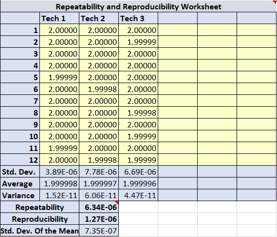
Repeatability and Reproducibility between technicians.

Repeatability and Reproducibility between technicians – This should only need to be performed once per every parameter on the scope of accreditation and be conducted amongst all technicians who perform calibrations using the equipment. This example uses three technicians recording readings at the same measurement point. The readings were taken in mV/V and were then converted to force units. Repeatability between technicians can be found by taking the square root of the averages of the standard deviation of readings of technicians. Reproducibility between technicians is found by taking the standard deviation of the averages of readings for each technician. Per VIM 2.24 (3.7, Note 2) reproducibility condition of measurement reproducibility condition - the condition of measurement out of a set of conditions that includes different locations, operators, measuring systems, and replicate measurements on the same or similar objects and MSA 4th Edition states “Reproducibility This is traditionally referred to as the "between appraisers" variability.
Reproducibility is typically defined as the variation in the average of the measurements made by different appraisers using the same measuring instrument when measuring the identical characteristic on the same part.” In a typical force laboratory, we do not have the same machines in different locations or different measuring systems. A typical force laboratory will have several machines, and each machine has its own set of characteristics where different operators need to be compared using the same instrument. Therefore, we commonly look at the reproducibility between the operators as a component of our uncertainty budget. The reproducibility in this example is the standard deviation of the averages. The result of throughput is typically a calibration certificate with multiple readings.
Additional Error from misalignment. All deadweight frames should be leveled to within 0.1 degrees or better. Any misalignment of more than 0.01 degrees will have a significant impact on the reproducibility of the device when positioned differently (rotated) in the machine.
Conclusion:
Calibration and Measurement Capability (ILAC-P14): A CMC is a calibration and measurement capability available to customers under normal conditions. If the deadweight machine is designed properly, the CMC with all the uncertainty contributors listed above should be capable of achieving 16 ppm or better. The newer Morehouse machines designed with more rigidity and the larger weights at the top of the deadweight stack have demonstrated that 16 ppm or better is achievable.
For more information on our deadweight machines, please click here.
I take great pride in our knowledgeable team at Morehouse, who will work with you to find the right solution. We have been in business for over a century and focus on being the most recognized name in the force business. That vision comes from educating our customers on what matters most and having the right discussions. Morehouse will not commit to providing a system if we cannot meet your expectations.
To learn more, watch our video on the Morehouse Deadweight Machine – The most accurate way to calibrate a load cell.
If you enjoyed this article, check out our LinkedIn and YouTube channel for more helpful posts and videos.
Everything we do, we believe in changing how people think about force and torque calibration. We challenge the "just calibrate it" mentality by educating our customers on what matters and what causes significant errors, and focus on reducing them.
Morehouse makes simple-to-use calibration products. We build awesome force equipment that is plumb, level, square, rigid, as well as provide unparalleled calibration service with less than two week lead times.
Contact us at 717-843-0081 to speak to a live person or email info@mhforce.com for more information.


