Top 5 Specifications to Consider for Load Cell Accuracy
One of the most important considerations when purchasing a load cell is its accuracy. However, a load cell datasheet typically does not contain all the specifications needed to determine an accuracy statement.
Which specification on a typical datasheet is most important? Do all specifications impact accuracy? Does it matter how the specification is expressed?
The top five specifications for accuracy are non-linearity, static error band, non-repeatability, creep, and temperature range compensated. Individually, each specification is a piece of the puzzle, and together they provide a clearer picture of load cell accuracy.
1: Non-Linearity
The most common accuracy-related specification is non-linearity. However, the specification can be measured with different methods and expressed differently. Some manufacturers prefer a more conservative approach using simple algebra, and others use higher-order equations that make the products look better.
For force measurements, non-linearity is the algebraic difference between the output at a specific load and the corresponding point on the straight line drawn between the outputs at minimum load and maximum load. Normally it is expressed in units of % of full scale (% FS). It can also be expressed in units of % of rated output (% RO), which is the output corresponding to capacity, equal to the algebraic difference between the signal at minimum load plus capacity and the signal at minimal load. If the percentage is 0.02 % of the full scale, then the maximum percentage error would be 0.2 % at 10 % of the range.
To calculate non-linearity the conservative way, measure the difference in the Y-intercept between the baseline and a parallel line passing through the maximum deviation point.
To use this method, first calculate the slope of the baseline, which is the line passing through the two endpoints.

Figure 1: Non-Linearity with Baseline
Next, find the maximum deviation at the X-midpoint, which typically has the largest error between the actual values taken and the calculated baseline.
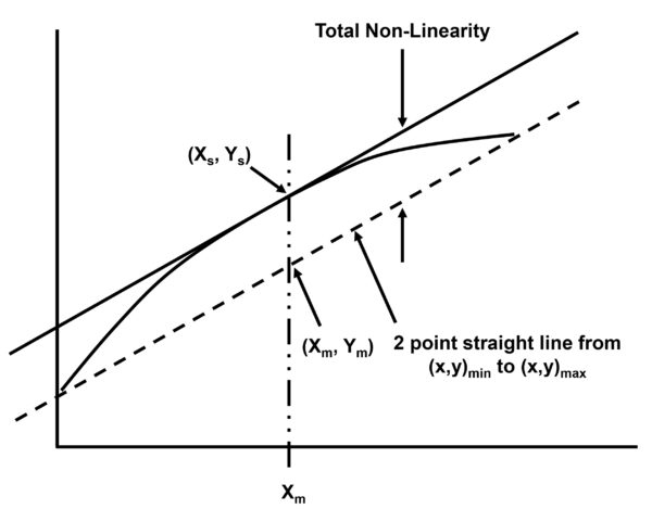
Figure 2: Midpoint Non-Linearity
The X-midpoint (Xm) is found in this equation:

If the Y-axis passes through zero, then the equation is:
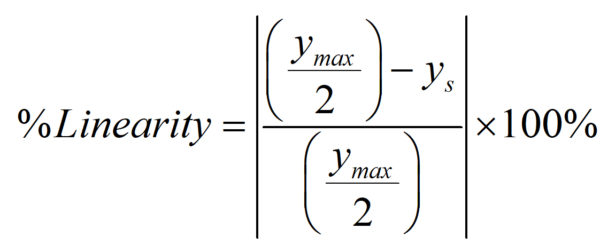
If the Y-axis does not pass through zero, then the equation is:

It is important to note that a manufacturer’s non-linearity specification is based on ideal conditions. It is characterized by one position, one location, one fixture setup, one temperature, and a one-time interval between readings. Therefore, if any of these conditions change, it could impact the non-linearity of the load cell. Manufacturers following the more conservative approach often use the worst-case non-linearity, which is typically between 40-60 % of full scale.
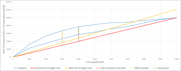
Figure 3: Load Cell Characteristics expressed via an expanded view in Excel. Typically, the BFSL does not start at zero.
2: Static Error Band
Another specification that defines the accuracy of a load cell is the static error band (SEB). It is the band of maximum deviations of the ascending and descending calibration points from a best-fit line through zero output. It includes the effects of non-linearity, hysteresis, and non-return to minimum load. SEB is normally expressed in units of % FS.
SEB is useful when the loading cycle requires both ascending and descending modes. If this is the only way the load cell is used, then the non-linearity specification holds little value. If the load cell is used to make ascending and descending measurements, then look at non-linearity for the ascending measurement use case and SEB when the use case requires a combined curve.
SEB is particularly useful with indicators that only have one span point. The SEB number will give an approximation of how far out what you are measuring in the range could be.
It is very useful for monitoring forces in various applications. When calculating Calibration and Measurement Capability (CMC), SEB may be used instead of non-linearity and hysteresis.
3: Non-Repeatability
When a load is repeatedly applied to a load cell, the output of the load cell can change slightly on each application. The non-repeatability specification defines the accuracy of a load cell by indicating how similar the results are when repeating measurements under identical conditions. Normally it is expressed in units of % of rated output (% RO).
Non-repeatability is defined as the maximum difference between output readings for repeated loadings under identical loading and environmental conditions. It is essential to have the same operator, adapters, indicator, calibrating machine, location, and temperature when measuring non-repeatability. The measurements should all be taken within a short period of time.
Non-repeatability cannot be compensated for. Therefore, a load cell with lower non-repeatability is preferred.
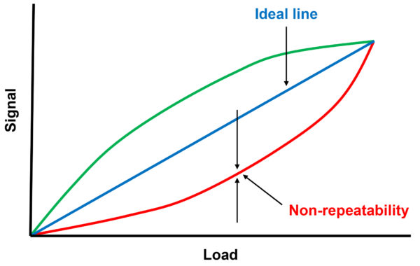
Figure 4: Non-repeatability
Non-repeatability is sometimes confused with reproducibility. Non-repeatability does not tell you how reproducible the load cell is, and sometimes manufacturers take liberties to confuse the two terms. For example, when a load cell is used in a different position or removed from the machine and placed elsewhere, that is called reproducibility.
Many manufacturers do not put a number on reproducibility. Morehouse does this by referencing the performance characteristics when tested following the ASTM E74 standard. A specification for reproducibility is Off-Center Load Sensitivity, which would be number 6 if the list was expanded to the top 6 specifications to consider for load cell accuracy.
4. Creep
A load cell’s creep specification is important for applications where a load cell remains under pressure for a long period. Creep is the change of a load cell’s output in real time while it is weighing an object. To determine the creep of a load cell, all environmental conditions and other variables should remain constant.
Creep recovery is defined in ASTM E74 as, “The change in deflection of the force-measuring instrument after the removal of force following a creep test.” ASTM goes on to say, “Creep Recovery is expressed as a percentage difference of the output change at zero force following a creep test and the initial zero force output at the initiation of the creep test divided by the output during the creep test. The zero-force measurement is taken at a time following the achievement of mechanical and electrical stability and a time equal to the creep test time. For many force-measuring instruments, the creep characteristic and the creep recovery characteristic are approximate mirror images.”
When force is applied to a load cell, it causes deformation to the load cell and strain gauge. Load cell creep happens when this deformation needs time to return to its original shape.
If a load is continually applied to a load cell, then the output will gradually change over time. Measurements should be taken at consistent time intervals to capture the true creep. For accuracy and repeatability, allow for a set amount of creep before taking readings.
Although creep can be minimized, it cannot be totally removed. To learn more, check out this blog on Load Cell Creep.
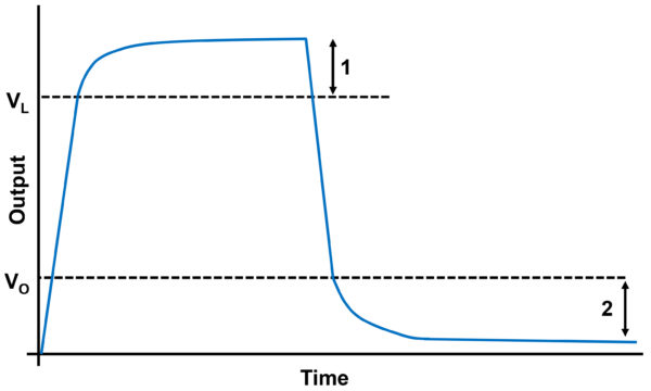
Figure 5: Load Cell Creep
5. Temperature Range Compensated
Since strain gauges and load cells are typically stainless steel, alloy steel, or aluminum, temperature changes will influence the accuracy of a load cell. Temperature affects the signal output and zero balance, which are indicated in the specifications Temperature: Effect on Sensitivity and Temperature: Zero Effect.
The specification Temperature Range Compensated is defined as the range of temperature over which the load cell is compensated to maintain rated output and zero balance within specific limits.
If a load cell is exposed to direct sunlight, nearby equipment that heats up the area, or extreme cold then hot, the dramatic temperature shifts can impact accuracy. Be sure to monitor the temperature of the area regularly and shield the load cell from direct sun. To meets specs, it is also essential that the entire load cell is at a uniform temperature. If there is a temperature differential across the load cell, errors can be much larger than the stated specifications.
Load cells that are compensated over a wider temperature range might be needed for specific applications. A load cell can be used in temperatures beyond its temperature-compensated range, but its specifications may be compromised.
It is important to note that any deviation in environmental conditions from the temperature the device was calibrated must be accounted for.
Getting the Load Cell Accuracy You Need
When load cells are used in practical applications, it is extremely difficult, and maybe impossible, to reproduce the conditions that were used to generate these accuracy specifications. However, by analyzing these top five specifications, you can gain a better understanding of your anticipated load cell accuracy.
Although load cell accuracy is often considered the most important factor when purchasing a load cell, the ultimate goal should be to understand the expected load cell performance. The best way to get a sense of this is to look at how well the load cell performs when calibrated to a standard such as ASTM E74, or ISO 376 while considering creep and temperature compensation specifications. Additional considerations are stability between calibration cycles and pairing the load cell with the appropriate indication system.
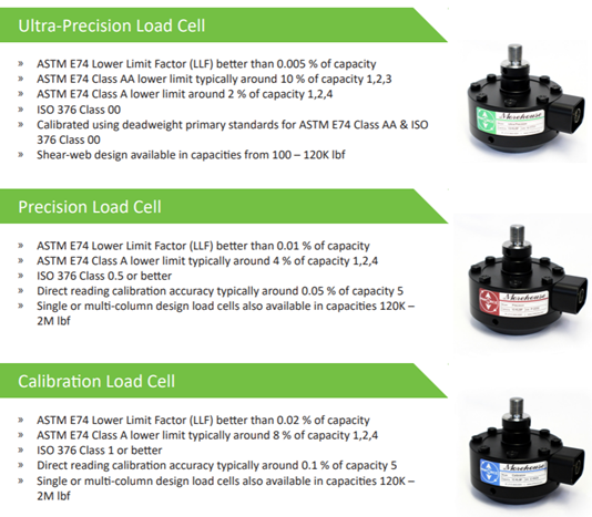
Figure 6: Morehouse Load Cells
Need help choosing a quality load cell that is appropriate for your application? Contact us and we can help you select a load cell to achieve the accuracy you need.
If you enjoyed this article, check out our LinkedIn and YouTube channel for more helpful posts and videos.


