

Load Cell Testing: How a Prototype Earns Its ASTM E74 Certificate
How Morehouse approaches load cell testing on a new prototype, from the temperature chamber to the deadweight machine to an ASTM E74 calibration, and why one aluminum prototype has us excited.
“Remember, kids, the only difference between screwing around and science is writing it down.” – Adam Savage, MythBusters
Load cell prototyping is the writing-it-down part. Morehouse has been making force measuring instruments since 1925, and we still build prototypes for every new design. A spec sheet is a promise. A prototype is where that promise meets a stack of deadweights that do not care what the spec sheet says.
This article walks through how we test a new load cell design: temperature compensation first, then a series of tests in our deadweight machines, and finally an ASTM E74 calibration that decides whether the cell gets a Class A loading range or goes back to the drawing board. The example is a 2 000 lbf aluminum shear web prototype we are still experimenting with. The early data is good enough that we wanted to share it, and honest enough to show what we have not figured out yet.
Why Prototype at All?
What if the gauges land a few thousandths off the center of the spoke? What if the adhesive cures differently on aluminum than it does on steel? What if the compensation resistor is sized for the wrong alloy? What if the element has a creep characteristic that nobody sees until a customer holds a load for twenty minutes?
Any one of those shows up as a number, and numbers are hard to argue with. Prototyping is how we find out which number it is before a customer does. A complaint is the most expensive calibration data you will ever collect.
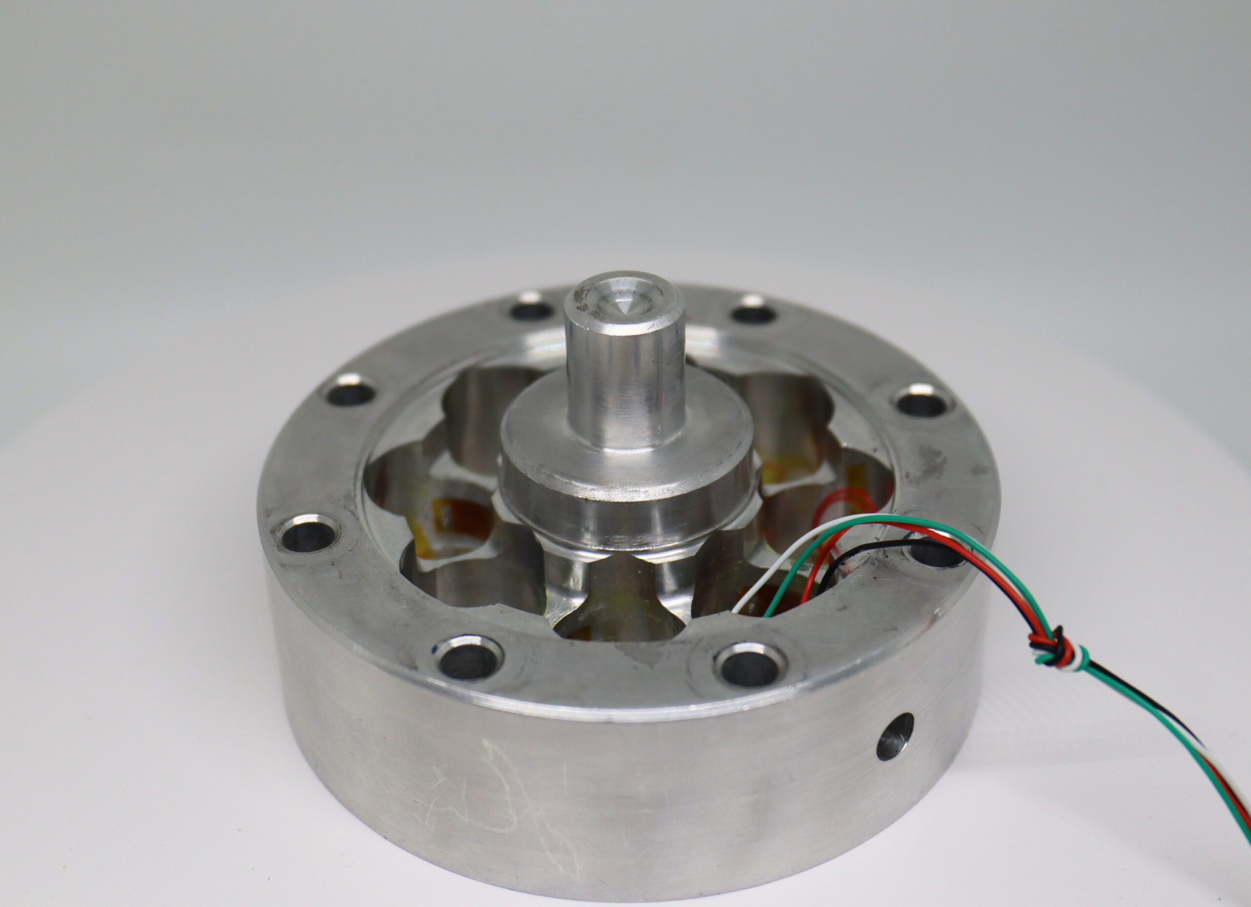
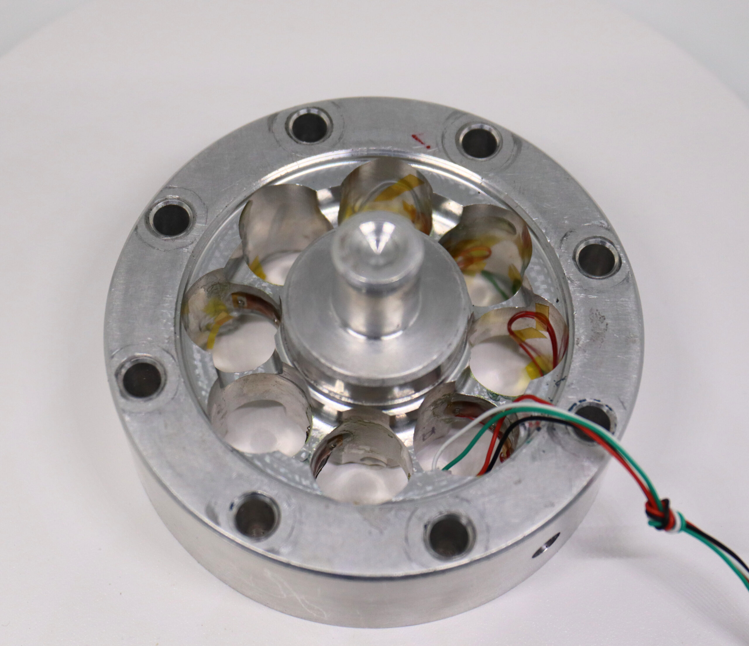
Figure 1. The 2 000 lbf aluminum shear web prototype element, gauged and wired, before the cover goes on. Eight strain gauges sit on the webs between the spokes.
Step 1: Temperature Compensation
A load cell that only reads correctly at 23 °C is a laboratory curiosity, not an instrument. Before any prototype sees a deadweight, it goes into our temperature chamber. We record zero and span at several temperatures across the compensated range, calculate the shift per degree, and size the compensation resistors (platinum or nickel, depending on the linearity of the temperature shift; if the shift runs the wrong direction, we switch to something with a negative temperature coefficient, such as a thermistor) so the cell holds its output as the temperature moves.
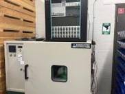
Figure 2. The Morehouse temperature chamber and switching rack. Thirty channels let us compensate a batch of cells in one run.
If you want the full story on oven aging, zero shift, span shift, and why the resistor choice matters, we covered it in our recent article on temperature compensating load cells. The short version is this: our shear web cells are compensated over 15 °F to 115 °F, with a sensitivity effect and a zero effect of 0.08 % per 100 °F each. A prototype that cannot hit that target does not move on to step 2.
People sometimes compare this step to baking a turkey. The difference is that with a turkey, you want it to come out different from how it went in.
Step 2: The Deadweight Gauntlet
Once a prototype is compensated, it goes to a deadweight machine. Morehouse deadweight primary standards are good to 0.002 % of applied force (expanded uncertainty, k = 2, approximately 95 % confidence), so whatever we see in the data is coming from the load cell, not the reference. That is the whole point of testing against deadweight. If the standard is noisier than the thing you are testing, you are guessing with extra steps.
Overload
First we load the cell to 150 % of capacity, 3 000 lbf, six times in a row, and record the zero after every cycle. Then we do it again. And again. The question is simple: does the zero come back?
On the very first overload, the zero moved 0.037 mV/V, roughly 1.9 % of span. Say what now? That sounds alarming until you look at the next five cycles, where the shift dropped to 0.0027, 0.0013, 0.0008, and 0.0006 mV/V. By the third set of six cycles, each overload moved the zero by only 0.0001 mV/V to 0.0004 mV/V, which is 0.005 % to 0.02 % of span. Our read is that the element, the gauges, and the adhesive were finding their seats on that first overload. The cell is settling in, not falling apart.
We are still deciding whether that first overload belongs in the manufacturing process as a conditioning step. That is one of the experiments still running.
Linearity, Hysteresis, Static Error Band, and Non-Repeatability
Next, five points up, five points down, from zero to 2 000 lbf in 400 lbf steps. This is the test that produces the numbers you see on a spec sheet, and it is where a prototype usually tells you whether the gauge placement worked. The aluminum prototype came back with:
Table 1. Initial deadweight characterization of the 2 000 lbf aluminum shear web prototype (n = 1 run, 0 lbf to 2 000 lbf in 400 lbf steps, ascending and descending).
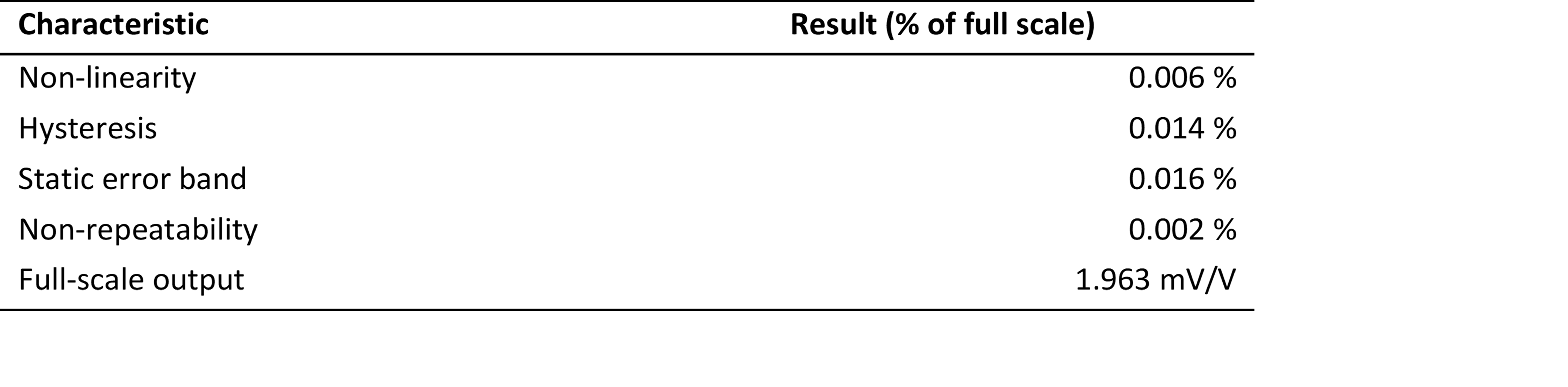
For reference, our Precision class cells are specified at 0.01 % of full scale and our Calibration grade at 0.02 %. A first-article aluminum element whose static error band lands between the two, before any tuning, is a good day. Aluminum has more hysteresis than tool steel, and 0.014 % is the number we are working on.
Creep
Load cells relax. Hold a force on one and the output drifts, and the drift is a property of the element material, the adhesive, and the gauge backing all working against each other. We hold the prototype at capacity for 20 minutes, reading every 30 seconds, then remove the load and watch the zero for another 20 minutes. Two runs on this prototype gave a 20-minute creep of 0.035 % and 0.023 % of full scale, with the zero returning to within 0.007 % and 0.004 % of full scale after unloading.
Those creep numbers are higher than we want. They are also exactly why we do this test on a prototype instead of discovering it on a customer’s tensile tester at the end of a five-minute hold. We may try a cryogenic treatment of the element in liquid nitrogen to see if it improves creep, though on other alloys and larger capacities it has not helped.
The Low End
Finally, we run 0 lbf to 100 lbf in 10 lbf steps, three times. On a 2 000 lbf cell, 10 lbf is 0.5 % of capacity, and most of the force world would tell you not to bother. We bother, because this is where the Class A loading range is won or lost. The three runs agreed to within 0.00001 mV/V to 0.00003 mV/V at every step. That kind of repeatability makes you check the data twice to be sure you did not paste the same run three times.
Step 3: The ASTM E74 Calibration
Everything up to this point is characterization. ASTM E74 is the exam. E74 requires at least 30 force applications across the range, spread over multiple runs, with the cell rotated between runs. We ran three runs from 0 lbf to 2 000 lbf in 200 lbf steps, with additional points at 50 lbf and 100 lbf. The deviations of each point from the fitted curve are pooled into a standard deviation, and the lower limit factor (LLF) is 2.4 times that standard deviation, expressed in force units. The LLF then sets the loading ranges:
- Class A loading range: 400 times the LLF up to capacity
- Class AA loading range: 2 000 times the LLF up to capacity
The prototype’s LLF came in at 0.0526 lbf.
Class A lower limit: 400 × 0.0526 lbf = 21.04 lbf, which is 1.05 % of capacity.
Class AA lower limit: 2 000 × 0.0526 lbf = 105.2 lbf, which is 5.26 % of capacity.
A Class A verified range of forces down to 1 % of capacity is the number that got our attention. Many of the load cells that come through our laboratory only become Class A somewhere between 5 % and 10 % of capacity, and a cell that is Class A from 1 % covers the ground that would otherwise take two or three instruments. Just over 1 % on an aluminum first article is something special, and we have three runs of deadweight data to back it.
Table 2. Zero-corrected output from the three E74 runs at selected points (n = 3 runs). Spread is the maximum minus minimum across runs.

One honest caveat. These results are from a prototype, measured over days, not years. We do not know the long-term stability yet, and stability is what separates a promising element from a reference standard. The cell goes back on the deadweight machine on a schedule, and we will publish the follow-up whether the news is good or not. Science is writing it down. It is also writing it down when it does not go your way.
What This Means When You Buy a Load Cell
Every load cell you own went through some version of this process, or it did not. If a manufacturer cannot tell you the creep, the overload behavior, or the lower limit of the Class A loading range on their own deadweight, they are letting you run the prototype test on their behalf. You just do not get paid for it.
So ask. Ask for the LLF. Ask what the Class A lower limit is as a percentage of capacity, because a 10 000 lbf cell that is only Class A from 1 000 lbf cannot be used for Class A work on anything below 1 000 lbf, no matter what the label says. Ask whether the cell was compensated in a chamber or on a spreadsheet. If the answer is a long pause, you have learned something useful, and it did not cost you a calibration.
We will keep experimenting with this one. If you want to talk about what a 1 % Class A range would do for your laboratory, reach out. We promise to write it down.
Load Cell Testing: How a Prototype Earns Its ASTM E74 Certificate Conclusion - About Morehouse
We believe in changing how people think about Force and Torque calibration in everything we do, including, "Load Cell Testing: How a Prototype Earns Its ASTM E74 Certificate"
This includes setting expectations and challenging the "just calibrate it" mentality by educating our customers on what matters and what may cause significant errors.
We focus on reducing these errors and making our products simple and user-friendly.
This means your instruments will pass calibration more often and produce more precise measurements, giving you the confidence to focus on your business.
Companies around the globe rely on Morehouse for accuracy and speed.
Our measurement uncertainties are 10-50 times lower than the competition, providing you with more accuracy and precision in force measurement.
We turn around your equipment in 7-10 business days so you can return to work quickly and save money.
When you choose Morehouse, you're not just paying for a calibration service or a load cell.
You're investing in peace of mind, knowing your equipment is calibrated accurately and on time.
Through Great People, Great Leaders, and Great Equipment, we empower organizations to make Better Measurements that enhance quality, reduce risk, and drive innovation.
With over a century of experience, we're committed to raising industry standards, fostering collaboration, helping with understanding risk, and delivering exceptional calibration solutions that build a safer, more accurate future.
Contact Morehouse at info@mhforce.com to learn more about our calibration services and load cell products.
Email us if you ever want to chat or have questions about a blog.
We love talking about this stuff. We have many more topics other than, "Load Cell Testing: How a Prototype Earns Its ASTM E74 Certificate"
Our YouTube channel has videos on various force and torque calibration topics here.