

Load Cell Temperature Compensation: Why a Load Cell Has to Earn Its Temperature Rating
Check your tire pressure in a cold garage, then drive two hours on a hot highway and check it again. The number went up. Nothing leaked in and nothing leaked out. The tire is the same tire; only the temperature changed.
NASCAR crews live with the extreme version. A set of tires that grips on the warm-up laps is a different set forty laps into a hot afternoon, so on a hot day the crew chief schedules the change earlier. At 180 mph the cost of being wrong about temperature is the wall. A load cell on a test frame is not moving at 180 mph, but the shift is happening whether you measure it or not, and the stakes decide whether you can afford to find out the hard way.
A strain gauge load cell does the same thing, and it does it in two directions at once. Warm it up and the zero moves. Load it while warm and the output per unit of force moves too. If no one measured those shifts and designed them out, the certificate on the wall is only true at the temperature the lab happened to be on the day the certificate was written.
Many manufacturers lean on no compensation at all. They state a temperature range, quote a specification, and hope the cell stays close enough. This article explains what temperature does to a load cell, how load cell temperature compensation is done at Morehouse, and why the oven is the step that cannot be rushed.
What Temperature Does to a Load Cell
A load cell is a spring element with four (or more) strain gauges bonded to it and wired into a Wheatstone bridge. Force deflects the element, the gauges change resistance, and the bridge turns that change into a millivolt-per-volt output. Temperature gets into that chain in three places.
- The spring element gets softer. The modulus of elasticity of steel falls as it warms. The same force now produces more strain, and the cell reads high. For a steel element, ASTM E74 §9.2 puts the deflection change at 0.027 % of reading per °C (0.015 % per °F). That is three times the entire accuracy specification of a 0.005 % class cell for every degree Fahrenheit of change, and more than five times for every degree Celsius.
- The gauges and the wiring have their own temperature coefficients. Each gauge, each solder joint, and each length of copper jumper changes resistance with temperature. If those changes are not identical in every arm of the bridge, the bridge goes out of balance with no force applied. That is the zero shift.
- The gauge factor drifts. The sensitivity of the gauge alloy itself changes slightly with temperature. It partly offsets the modulus change, but it does not cancel it.
Two effects come out of this, and the industry specifies them separately:
- Temperature effect on zero. How far the no-load output moves per degree, stated as a percentage of rated output.
- Temperature effect on output (span). How far the sensitivity moves per degree, stated as a percentage of the applied load.
A word on that second name. "Temperature effect on zero" sounds like something that only matters at no load, and a lot of people treat it that way: tare the cell, problem solved. It is not. The zero shift is an offset that rides along under every reading in the range. The only time a tare removes it is when the temperature holds still from the moment you tare to the moment you read, and the cell is truly at no load when you tare it. It never is. There is always a fixture, a top block, or an adapter sitting on it, and on a low-capacity cell the cell’s own weight is already a load. Rely on good compensation, not on the tare button.
Most Morehouse load cells carry a temperature specification of 0.0008 % of load per °F (0.0015 % per °C) on output and 0.0008 % of rated output per °F (0.0015 % per °C) on zero, over a compensated range of 15 °F to 115 °F (−9 °C to 46 °C). For comparison, ASTM E74 Note 11 recommends that the temperature effect on sensitivity not exceed 0.0030 %/°C (0.0017 %/°F) for Class AA use and 0.010 %/°C (0.0056 %/°F) for Class A; the Morehouse figure is half the Class AA value. Other manufacturers may be equivalent or worse, so read the data sheet rather than assuming.
One more thing about data sheets. Most manufacturers do not advertise that their load cells are temperature compensated; they assume you expect it and quietly do the work. The ones that put "temperature compensated" in the headline are, in our experience, often the less stable ones. Ignore the headline and compare the actual temperature specifications. When you see 0.05 %/°F or worse, that is usually a cell nobody spent labor compensating. The number is doing the talking, and it is saying "we skipped the oven."
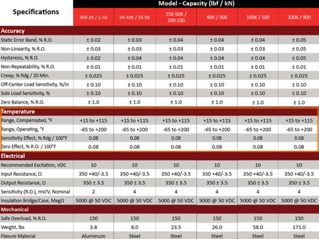
Figure 1. Morehouse shear web load cell specifications. The outlined temperature block gives the compensated range and a sensitivity and zero effect of 0.08 % per 100 °F (0.0008 %/°F, 0.0015 %/°C).
Load Cell Temperature Compensation Comes After the Gauges, Never Before
The order matters. Gauges are bonded, wired, and the bridge is completed first. Only then does temperature compensation begin, because every solder joint and every inch of copper added to the bridge changes what needs to be corrected. Compensating a bare element, then wiring it, is compensating the wrong thing. It is tuning the guitar and then changing the strings.
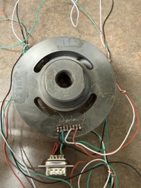
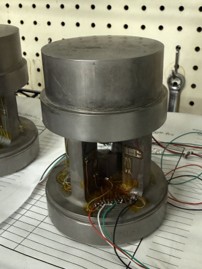
Figures 2 and 3. Left: a column-type load cell with gauges installed and wired, ready for the oven. Right: a shear web load cell wired to its terminal strip and connector. The fine copper jumpers in each arm must be kept as equal as possible so the zero does not move with temperature.
Our starting goal is to need no correction at all. If the copper in every arm of the bridge is matched, the resistance changes cancel and the zero stays put. When it works, no resistor has to be added. When it does not, the oven tells us.
The Oven: Aging, Stabilizing, and Measuring the Shift
Every cell goes into a temperature chamber connected to a multi-channel readout. The oven does two jobs.
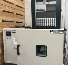
Figure 4. One of several temperature chambers at Morehouse used to check temperature compensation, with its 30-channel readout rack above it. Each load cell is read continuously while the chamber steps through its temperature points.
The first is aging. Heat cycling relieves residual stress in the adhesive, the solder, and the element itself. Things shift. We want them to shift now, in the oven, rather than six months from now on a customer’s bench.
The second job is measurement. We bring the chamber to a temperature and watch the output of every cell with no load applied. Here is where some take a shortcut: an hour in the chamber, one reading, move on. An hour is a guess. The element, the gauges, and the chamber air all reach temperature at different rates, and the only honest way to know the cell has settled is to monitor output versus time until the trace goes flat.
After stabilization we record the readings, then move to the next temperature and repeat. The result is a zero reading at each temperature for each cell. The difference between them, divided by the temperature span, is the temperature effect on zero.
Correcting What the Oven Finds
If the wiring is symmetric, the cell usually passes: the zero shift and span shift are inside the specification for that cell type, the balanced copper did its job, and nothing is added.
If a cell fails, we correct it with a temperature-sensitive resistor. For zero, a short length of copper or a small resistor goes into the bridge arm that will pull the shift back toward zero. For span, a platinum or nickel resistor is placed in series with the bridge excitation. These metals have a large, repeatable positive temperature coefficient: nickel about 0.6 % per °C (0.33 % per °F), platinum about 0.39 % per °C (0.22 % per °F). As the element warms and softens, the resistor warms too, its resistance rises, and the excitation reaching the bridge falls by the same proportion. The modulus loss and the excitation loss cancel.
The resistor is sized from the measured shift, not from a table. That is why the oven data has to be right. A resistor chosen from a one-hour reading that was still drifting corrects a shift that never existed.
Then the cell goes back in the oven and the whole sequence runs again, because adding a resistor adds solder joints and wire, and both are back in the bridge. Compensation is checked, not assumed.
Here is why "checked, not assumed" is not a slogan. A manufacturer we know of was building thousands of calibration-grade load cells for one project, running every cell through temperature, and seeing a 100 % pass rate. Then one day the pass rate was not 100 %. The cells were suddenly fifty times the specification, and nothing in the process had changed. After days of investigation it turned out their supplier had swapped the platinum resistors for ordinary resistors of the same nominal value. Same ohms, same part on the drawing, no temperature coefficient to speak of. The supplier figured nobody would know the difference. People who test things know the difference. Testing thousands of load cells through temperature is expensive. A customer returning millions of dollars of load cells can bankrupt a company, if those load cells do not bankrupt the customer first.
Uneven Heating, and the Connector That Will Not Settle
Everything above assumes the whole cell is at one temperature. Uneven heating is a different animal. A cell warmed on one side, sitting in direct sunlight or next to a hydraulic pump, can shift by an order of magnitude more than its temperature specification suggests, and two seemingly identical cells from the same batch can shift by different amounts. You will never see this in a chamber, because a chamber heats evenly and holds still. You see it on the rig.
One example comes up often enough to deserve a name: the hermetic connector with a glass-to-metal seal, common on US-made load cells. That connector is a thermal island bolted to the side of the element. In direct sun it heats faster than the body, drags the bridge with it, and will not stabilize until sunset. If a hermetic connector is not a hard requirement, do not specify one. The glass is also prone to microcracks that trap moisture, which adds its own errors over time. Even heating that is perfectly even can produce a large transient before the cell stabilizes, but that topic deserves its own article.
What This Means for Your Measurements
Start with a Morehouse cell rated at 0.0008 % of load per °F (0.0015 % per °C) on output. Your lab sits at 23 °C (73.4 °F); the shop floor where the cell gets used is 93 °F (34 °C), 20 °F (11 °C) warmer. The span shift is 20 °F × 0.0008 %/°F = 0.016 % of load. On a 100 000 lbf reading, that is 16 lbf.
Now take a cell with no compensation at all. ASTM E74 §9.2 puts the deflection change for bare steel at 0.015 % per °F (0.027 % per °C); the gauge factor offsets a little of it, so treat this as the upper bound. The same 20 °F gives 0.3 % of load, or 300 lbf, almost twenty times the compensated error, and nothing on the certificate warns you.
The same math plays out over a year on one bench with no climate control. In January the room is 43 °F (6 °C), 30 °F (17 °C) below the 73.4 °F (23 °C) calibration temperature, and the uncompensated cell reads low: 30 °F × 0.015 %/°F = 0.45 % of load, or 225 lbf at 50 000 lbf. In July the room hits 93 °F (34 °C) and the cell reads 0.3 % high, or 150 lbf. The cell moved 375 lbf between those two days and nobody touched it. A compensated cell would move 12 lbf and 8 lbf. Both cells have a certificate; only one is still telling the truth in January.
Now put the uncompensated cell on an outdoor rig in the desert: 110 °F (43 °C) days, 60 °F (16 °C) nights, a 50 °F (28 °C) swing. On span alone, 50 °F × 0.015 %/°F = 0.75 % of load, so 100 000 lbf applied at noon and again at midnight reads 750 lbf apart. Zero drifts too. A zero shift of 0.005 % of rated output per °F (0.009 % per °C), common for mismatched copper, adds another 250 lbf. Noon and midnight can disagree by 1 000 lbf on a cell that promises 5 lbf. The compensated cell on the same rig moves about 40 lbf on span and 40 lbf on zero. These are theoretical numbers, but they show the scale: once the cell leaves the room it was calibrated in, temperature, not the accuracy class, is the biggest error.
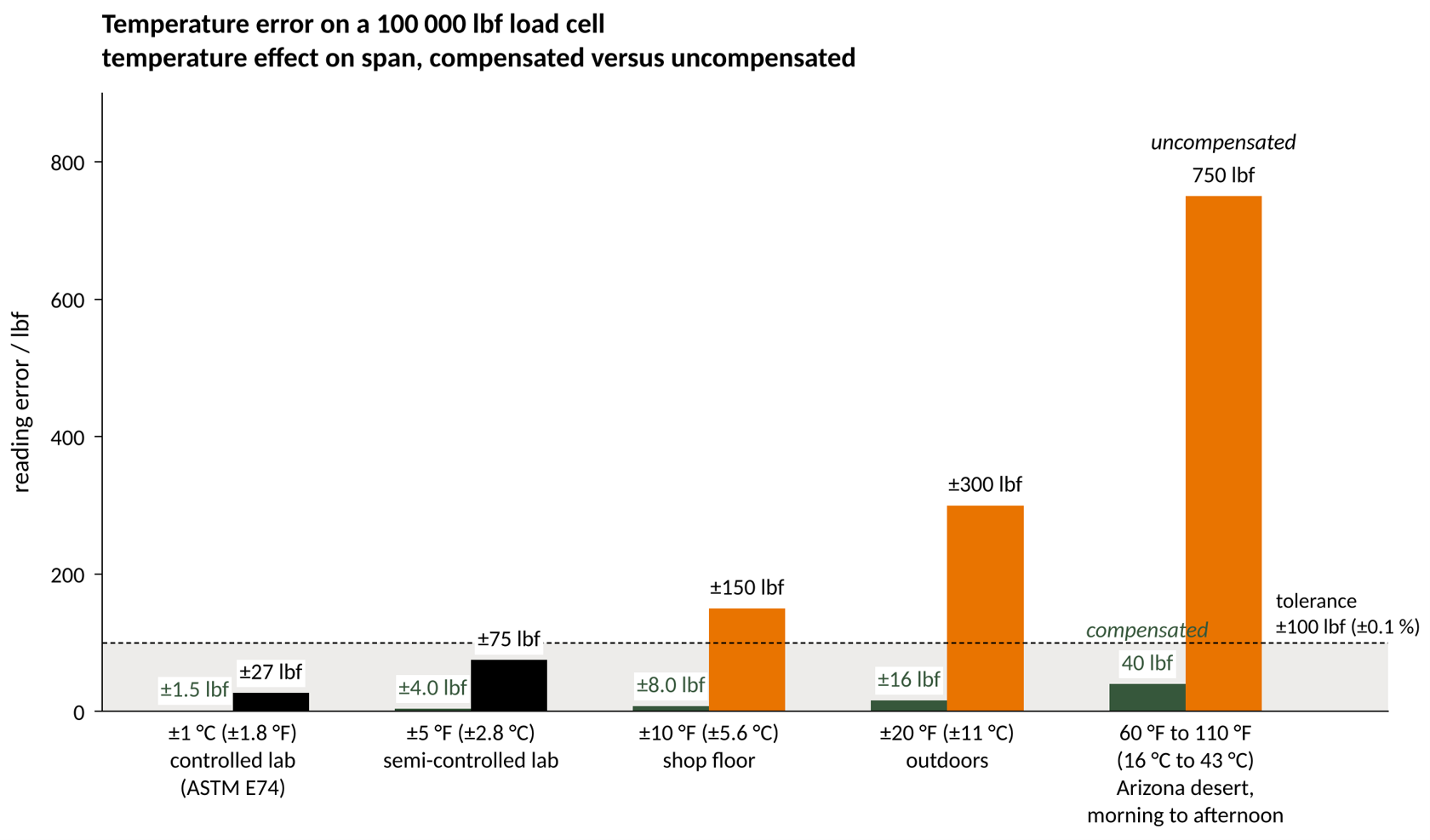
Figure 5. Reading error on a 100 000 lbf load cell from the temperature effect on span alone, compensated (0.0008 %/°F) against uncompensated (0.015 %/°F), for five temperature conditions. Zero effect excluded; tolerance ±100 lbf (±0.1 %).
What if your cell is a 0.005 % class instrument and you never thought about where it is used? What if the certificate was issued at 23 °C (73.4 °F) and the cell lives at 85 °F (29 °C)? What if the lab never asked? Any time the use temperature is not the calibration temperature, the temperature effect belongs in your uncertainty budget. The manufacturer’s compensation spec is the number that goes in it.
Here is where the error starts changing decisions. Say the job is to check that a test frame applies 100 000 lbf within ±0.1 %, or ±100 lbf. Every result is a pass or a fail, and every verdict can be wrong. Calling a nonconforming result good is a false accept; calling a conforming result bad is a false reject. Their probabilities, PFA and PFR, are what the measurement uncertainty and, when needed, a guard band are there to control. That only works if the uncertainty budget is complete.
The compensated cell on the 93 °F (34 °C) shop floor shifts 16 lbf. Put that in the budget and the expanded uncertainty lands around 25 lbf to 30 lbf against a 100 lbf tolerance: the test uncertainty ratio is still better than 3:1, a small guard band holds PFA down, and a frame truly within 70 lbf of nominal passes. Temperature cost a few lbf of acceptance window and nothing else.
The uncompensated cell on the same floor shifts 300 lbf, three times the tolerance. A frame applying exactly 100 000 lbf reads 100 300 lbf and fails. Flip it: a frame applying 99 700 lbf, 300 lbf out of tolerance, reads 100 000 lbf and passes. That is a false accept, and nothing in the budget catches it. Temperature did not widen the uncertainty; it moved the whole result off center, so a guard band built from that budget is a guard band around the wrong number, and any PFA the lab reports is wrong in the direction that lets bad frames through.
Temperature belongs on the same checklist as the errors people already look for: adapters that differ from the ones used at calibration, loading through the threads instead of the shoulder, a different cable length or excitation voltage, an indicator that was never paired with the cell. Most of those are fixed once the setup is fixed. Temperature keeps changing after everything else is bolted down.
What to Do
- Read the temperature specification on your load cell, not just the accuracy class. Ask the manufacturer whether the cell was individually compensated or whether the number is a design value.
- Record the temperature at calibration and at use. ASTM E74 asks for the calibration temperature on the report for a reason.
- Put the temperature effect in your uncertainty budget when the two temperatures differ, and let the number decide whether the difference matters.
- If you need the cell to hold its specification outside a controlled lab, buy one that spent time in an oven and was corrected from data.
- Skip the hermetic glass-to-metal connector unless a specification forces it on you, and keep the cell out of direct sun. A cell heated from one side is not at any temperature on the data sheet.
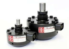
Figure 6. Morehouse shear web load cells. Each one is compensated after gauging, in the oven, from its own measured shift.
A load cell that was compensated from measured shifts, after its gauges were installed, after it stopped drifting, is a load cell that gives you the same answer in January and July. That is why we spend the extra time in the oven. Everyone talks about the weather; we are one of the few who do something about it, one resistor at a time.
Load Cell Temperature Compensation: Why a Load Cell Has to Earn Its Temperature Rating Conclusion - About Morehouse
We believe in changing how people think about Force and Torque calibration in everything we do, including, "Load Cell Temperature Compensation: Why a Load Cell Has to Earn Its Temperature Rating"
This includes setting expectations and challenging the "just calibrate it" mentality by educating our customers on what matters and what may cause significant errors.
We focus on reducing these errors and making our products simple and user-friendly.
This means your instruments will pass calibration more often and produce more precise measurements, giving you the confidence to focus on your business.
Companies around the globe rely on Morehouse for accuracy and speed.
Our measurement uncertainties are 10-50 times lower than the competition, providing you with more accuracy and precision in force measurement.
We turn around your equipment in 7-10 business days so you can return to work quickly and save money.
When you choose Morehouse, you're not just paying for a calibration service or a load cell.
You're investing in peace of mind, knowing your equipment is calibrated accurately and on time.
Through Great People, Great Leaders, and Great Equipment, we empower organizations to make Better Measurements that enhance quality, reduce risk, and drive innovation.
With over a century of experience, we're committed to raising industry standards, fostering collaboration, helping with understanding risk, and delivering exceptional calibration solutions that build a safer, more accurate future.
Contact Morehouse at info@mhforce.com to learn more about our calibration services and load cell products.
Email us if you ever want to chat or have questions about a blog.
We love talking about this stuff. We have many more topics other than, "Load Cell Temperature Compensation: Why a Load Cell Has to Earn Its Temperature Rating"
Our YouTube channel has videos on various force and torque calibration topics here.