Load Cell Stability – How It Can Kill Your Uncertainty Budget
Load cells are a combination of metal, strain gauges, adhesive, and more. Like humans, every measuring instrument is subject to aging. Load cells age from mechanical stress or fatigue, and over time this ensures that there will be some instability in the system.
Some common factors that impact load cell stability or system stability include:
- The meter used with the system - Just like load cells, the electronic components can drift
- The amount of usage of the load cell
- The material and strain gauges used to make the cell
- If the load cell has been loaded past capacity, and how many times it has been loaded
- Exposure to higher temperatures
- Amount of creep in the Load Cell
- Strain Hardening - This is why load cells get better with age until they do not.
- Variations in applying the strain gauges
- Using different cables, and connections than what was used during calibration
- Adapters - generally, calibration adapters do not impact stability, though changing the hardness and types of adapters can impact the calibration results. More information on adapters influencing calibration results can be found here.
The list of factors that impact load cell stability can continue. There are thousands of variables that can cause a change in load cell stability. Having a documented process and purchasing load cells from reputable manufacturers is a start to controlling the load cell stability.
One resource to learn more about strain gauges can be found by Vishay, titled Stress Analysis Strain Gages.
Not every source of load cell stability can be prevented. However, the impact of load cell stability can be detected and corrected by setting the appropriate calibration cycle, implementing statistical process controls, and following generally accepted good practice guidelines.
Load cell stability or drift is usually assumed to be the change in the entire cell system from one calibration cycle to the next.
It is the relative standard uncertainty of a reference force transducer’s long-term instability. In an uncertainty budget, load cell drift can be referred to as either the reference standard instability or the reference standard stability.
Load cell stability can impact the following:
- Potentially consume your uncertainty budget
- Cause the force measuring device to be out of tolerance
- Cause all measurements between the last calibration and the current calibration to be recalled
- Raise the accuracy specification of the system
Calibrating load cells for more than 50 years, Morehouse has observed all kinds of instabilities from different manufacturers. Most load cells are categorized as either general purpose or those calibrated by more stringent standards, such as ASTM E74 or ISO 376.
We will discuss both load cell types and their typical instability characteristics. In each case, we will start with the general uncertainty contributors, then progress to what we usually observe and recommend improvement.
The systems are each broken down into Good, Common, and Bad. Systems that fall into the Good category are usually those by reputable manufacturers who understand load cells and indicating systems.
The Common category may consist of suboptimal combinations, such as an excellent load cell and an average indicator or an excellent indicator and an okay load cell. In the Poor category, one or both components are probably unsuitable for the end user’s overall uncertainty needs.
Typically, general-purpose load cells are more inexpensive and paired with indicating systems contributing to drift or system stability. The requests we see on these systems are generally for a 10-pt. calibration. The accuracy specifications are usually 0.05 % to 1 % of full scale.

Figure 1: Typical Instability Numbers for Various Load Cells
The long-term instability of the reference force transducer is determined either from previous calibrations or by estimations of similar systems until the actual values can be obtained. Figure 1 above shows the instability Morehouse typically observes on general-purpose load cells.
Next, we will discuss calculating expanded uncertainty and how reference standard stability (or instability) affects overall expanded uncertainty.
General Purpose Load Cells
Typical contributions for the CMC uncertainty of General Purpose load cells are:
Type A Uncertainty Contributions
1) Non-Repeatability
2) Repeatability or Non-Repeatability of the Reference Standard.
3) Repeatability of the Best Existing Device (and technician)
4) Repeatability and Reproducibility
Type B Uncertainty Contributions
5) Resolution of the Best Existing Device
6) Reference Standard Resolution* If Applicable
7) Reference Standard Uncertainty
8) Reference Standard Stability (load cell stability)
9) Environmental Factors
10) Other Error Sources
11) Specified Tolerance * If Not Listed and making ascending measurements only. If making Ascending and Descending Measurements Use Static Error Band (SEB) or a combination of Non-Linearity and Hysteresis. If the force measuring device is calibrated with an indicator and set up to have a tolerance, then it may not be necessary to include non-linearity or SEB.
*Note: if the device is going to be used at points different from the points it was calibrated at, than SEB, Non-Linearity, or Hysteresis may need to be used.
12) Hysteresis * (Only if the Device is Used to Measure Decreasing Forces and SEB was not used)
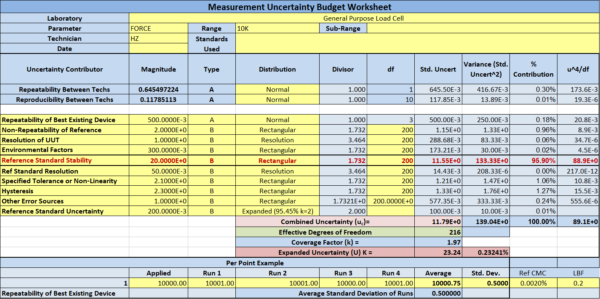
Figure 2: Expanded Uncertainty Budget with 0.2 % instability
With general-purpose load cells, observing systems with accuracy specifications lower than the instability observed from one calibration to the next is common. If the accuracy requirement is for 0.1 % of full scale and the instability from one calibration to the next is 0.2 %, it becomes nearly impossible to claim 0.1 % accuracy as your tolerance.
Figure 2 shows the uncertainty of 0.2 % instability on a 10,000 lbf load cell. This accounts for approximately 95.90 % of the uncertainty contribution.
When accounting for reference standard stability in an uncertainty budget, stability can be treated as type A or B. Most calibration laboratories claim instability as a type B uncertainty contributor with a rectangular distribution. This means that instability of 0.2 % would be divided square root of 3 (or 1.732), about 0.115 %.
Now let’s think about that. A calibration laboratory claims 0.1 % accuracy on their scope, and their device’s instability accounts for 115 % of their accuracy statement alone. This is a case of system stability accounting for more than the 100 % allowable.
The solution to this problem is often simple. Either shorten the calibration frequency or purchase better equipment. This could mean upgrading the indicator, load cell, or both.
Next, let’s assume the end-user decided it would be much less expensive to buy a better load cell than to shorten the calibration interval. A year after the purchase, the reference standard stability is observed to be 0.05 % or 5 lbf on a 10,000 lbf load cell.
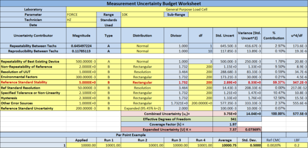
Figure 3: Expanded Uncertainty Budget with 0.05 % instability
In this example, shown in Figure 3, the Reference Standard Stability (load cell stability) still is the most significant contribution to the Expanded uncertainty. However, the end-user can now claim 0.1 % of full scale and have room to maintain the accuracy from one calibration to the next. The instability can go as high as 0.077 %, and they could still be within the 0.1 % of full scale!
Note: Morehouse recommends our Calibration Grade Load Cells and a G501F or C705P Indicator for General Purpose Calibration.
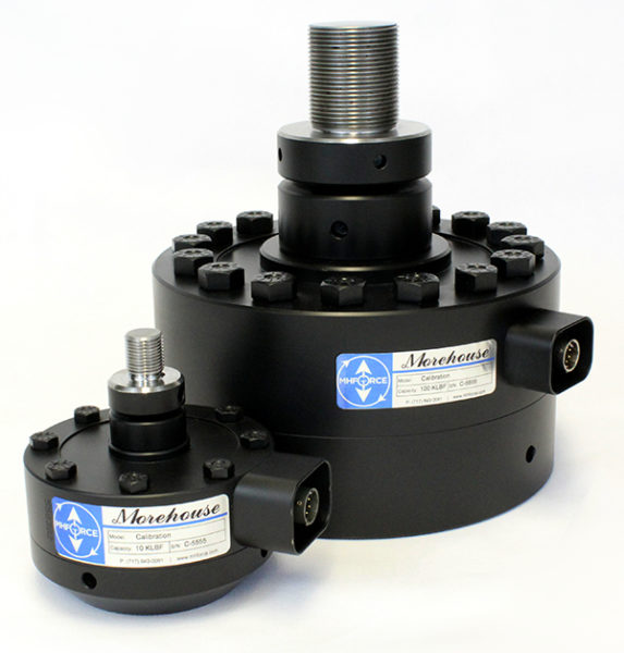
Figure 4: Morehouse Calibration Grade Load Cells
The Morehouse calibration grade load cell with G501F indicator will typically maintain accuracy of 0.1 % of full-scale year over year, with load cell stability accounting for about 0.05 % of overall accuracy. If an accuracy of 0.05 % or better is required, we recommend a different meter, most likely the C705P or the Morehouse 4215.
Devices Calibrated following the ASTM E74 Standard (Usually Metrological Grade Load Cells and Indicators)
Note: This section can be used for the devices calibrated following ASTM E74 and for ASTM E4 and other calibrations to determine the CMC uncertainty. The ASTM E4 Annex gives additional detail on calculating the measurement uncertainty for the ASTM E4 verification/calibration.
The contributions for the CMC uncertainty are:
Type A Uncertainty Contributions
1) ASTM LLF reduced to 1 Standard Deviation (ASTM LLF is reported with k= 2.4)
2) Repeatability with the Best Existing Device
3) Repeatability and Reproducibility
Type B Uncertainty Contributors
1) Resolution of the Best Existing Device
2) Reference Standard Resolution* If Applicable
3) Reference Standard Uncertainty
4) Reference Standard Stability (Load Cell Stability)
5) Environmental Factors
6) Other Error Sources
All uncertainty contributions should be combined, and the Welch-Satterthwaite equation should be used to determine the effective degrees of freedom for the appropriate coverage factor for a 95 % confidence interval. Figure 5 below shows typical numbers Morehouse has observed regarding instability. ASTM calls this “change from previous”.

Figure 5: Typical Instability Numbers for ASTM Load Cell Calibrations
Note: In this example, anything over 0.16 % of the applied force is bad because we are discussing ASTM calibrations and section 11.2.1 of ASTM E74-18 states, “Force-measuring instruments shall demonstrate changes in the calibration values over the range of use during the recalibration interval of less than 0.032 % of reading for force-measuring instruments and systems used over the Class AA verified range of forces and less than 0.16 % of reading for those instruments and systems used over the Class A verified range of forces.”
The assumption is that most end-users are using the force-measuring instruments for calibration following ASTM E4 and would like to comply with the ASTM E74 standard. That requires a calibration interval of two years.
Section 11.2.2 states, “Force-measuring instruments not meeting the stability criteria of 11.2.1 shall be recalibrated at intervals that shall ensure the stability criteria are not exceeded during the recalibration interval.” The standard says that if the criteria are unmet, the calibration interval must be shortened until it is met.
Through our experience, we have rarely observed Bad load cells meet the stability criteria if the calibration interval was shortened to one year. If stability is higher than 0.16 % and everything else remains constant (e.g., the cell has not been overloaded), then the recommendation is to replace the load cell.
Let’s compare two examples by comparing a reference standard stability of 0.16 % (Figure 6) to a typical Morehouse HADI system with Ultra-Precision Class or a better load cell with 0.01 % stability (Figure 7).
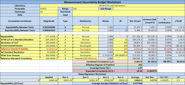
Figure 6: ASTM E74 Expanded Uncertainty with 0.16 % load cell stability
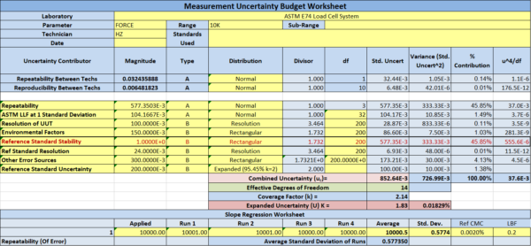
Figure 7: ASTM E74 Expanded Uncertainty with 0.01 % load cell stability
The actual load cell in this test is a Morehouse Ultra Precision 10,000 lbf load cell with an ASTM lower limit factor (llf) of 0.25 lbf. Assuming everything else remains the same, the Reference Standard Stability (load cell stability) is the largest contributor to uncertainty in both scenarios. Often, this isn’t the case. Load cells with bad instability often have much higher llfs than better load cells. A load cell with 0.16 % stability usually has an llf worse than 2 lbf.
However, this blog aims to show the impact of stability on a load cell system and how it should impact your decisions when purchasing a load cell system. The system will probably not meet your accuracy requirements if stability is bad. In general, repeatability, reproducibility, and stability are the most important characteristics when evaluating a load cell system.
Adapters play a considerable role in actual results, and careful attention to purchasing the right adapters must also be considered. Morehouse has a technical paper that can be downloaded here for more information on the proper adapters.
For ASTM E74 or ISO 376, Calibration Morehouse recommends our Precision Grade Load Cells and either a Morehouse HADI or Morehouse 4215
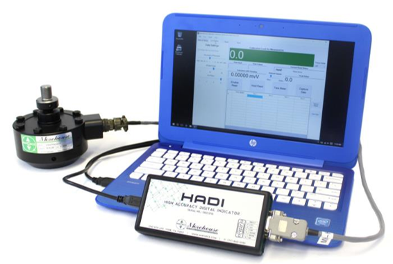
Figure 8: Morehouse HADI calibration system
The Morehouse Ultra-Precision Load Cell with the HADI system will typically maintain an ASTM Class A verified range of forces from 2 % of capacity (accuracy at the time of calibration of 0.005 %) or better year over year. Load Cell Stability accounts for 50 % or less of the overall uncertainty budget, usually below 0.02 % of applied force (0.01 % or better instability from year to year).
Load Cell Stability Conclusion
If I can stress anything, reference standard stability (load cell stability) must be considered in any uncertainty budget, and overall system accuracy should be adjusted accordingly. Manufacturers often highlight short-term accuracy and discount drift from their accuracy specifications.
We know that load cell stability largely depends on how equipment is used, the number of load cycles, the age of the material, the strain gauge bond, electronics, and more. Instability is best quantified when comparing one calibration against another, with all other things equal. Load cell stability is often overlooked and should not be discounted when considering system accuracy.
Morehouse - The accuracy in precise, low bias, true, right, strictly correct, exact, accurate force measurements! 🙂
If you enjoyed this article, check out our LinkedIn and YouTube channel for more helpful posts and videos.
Everything we do, we believe in changing how people think about force and torque calibration. We challenge the "just calibrate it" mentality by educating our customers on what matters and what causes significant errors, and focus on reducing them.
Morehouse makes simple-to-use calibration products. We build awesome force equipment that is plumb, level, square, and rigid and provide unparalleled calibration service with less than two-week lead times.
Contact us at 717-843-0081 to speak to a live person or email info@mhforce.com for more information.
# load cell stability


