ASTM E74 is Not the Same as ISO 376
Morehouse has performed ASTM E74 and ISO 376 calibrations for over fifteen years. We have been calibrating in accordance with the ASTM E74 standard since its introduction in 1974 and performing ISO 376 calibrations since sometime in early 2000. Before early 2000, ISO-376 was a DIN standard that later became EN-10002-3 and ISO 376 in the 1990s. Until recently, we assumed that the rest of the world and the force community knew that the standards were completely different and that either standard could not be substituted for another. However, we have learned that not only are some laboratories providing field calibrations by intermixing and using an ASTM E74 calibration to certify a tensile machine to ISO 7500, but that several organizations throughout the world are not aware that the standards are vastly different in the criteria requirements. The basics are that if ISO 7500 is the requirement, then calibration needs to be performed in accordance with ISO 376 on the force-proving instruments used to certify the tensile machine. If ASTM E74 is the requirement, then the elastic force-measuring instrument needs to be calibrated in accordance with the ASTM E74 standard. The differences have already begun to emerge with the subtle use of terminology.
ASTM E74 and ISO 376
ASTM E74-13a is titled Standard Practice of Calibration of Force-Measuring Instruments for Verifying the Force Indication of Testing Machines
ISO 376:2011 Metallic materials — Calibration of force-proving instruments used for the verification of uniaxial testing machines.
Selection of Forces
ASTM E74 Requires at least 30 force points to be selected and typically three runs of data each with a force point taken at about a 10 % interval. If the Class A or Class AA loading range is anticipated to be less than the first non-zero force point, then a point equal to at least 400 times the resolution for Class A or 2000 times the resolution for Class AA needs to be added to the calibration forces selected. While ISO 376 requires at least 8 force points throughout the range and at least 4 runs of data and a creep test if the force-measuring instrument is to be used for incremental loading only. If the force-proving instrument is to be used for both incremental and decremental loading, then two extra runs of data are taken making the total of runs 6. ISO 376 does not allow the first test point to be less than 2 % of the measuring range and has classifications that state the first point cannot be less than 4000 times the resolution for Class 00, 2000 times the resolution for Class 0.5, 1000 times the resolution for Class 1, and 500 times the resolution for class 2.
Creep Tests
ASTM E74 requires a creep test if the data is analyzed with Method A which allows the trailing zero to be ignored, whereas ISO 376 requires a creep test if only incremental loads are applied. More information on the creep tests can be found in each of the standards
Time requirements for application of forces
ASTM E74 does not reference a specific set time a force should be applied before the point is taken while ISO 376 states in section 7.4.3 “The time interval between two successive loadings shall be as uniform as possible, and no reading shall be taken within 30 s of the start of the force change.
Determination of deflection
ASTM E74 allows for Method A which involves ignoring the trailing zero and Method B which involves using an acceptable method such as average zero or interpolation of zero. ISO 376 defines deflection as the difference between a reading under force and a reading without force.
Curve Fitting
ASTM E74 uses the observed data and fits the data to a curve. Most of the time a second-degree equation is used, and ASTM E74 allows up to a 5th-degree equation assuming the resolution of the device is over 50,000 counts, and an F test is passed per Annex A1. ISO 376 allows the use of curves up to a third degree only.
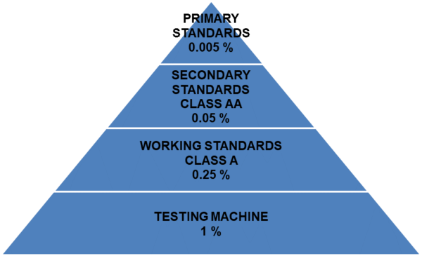
Figure 1 ASTM E74 Test Accuracy Ratio Pyramid
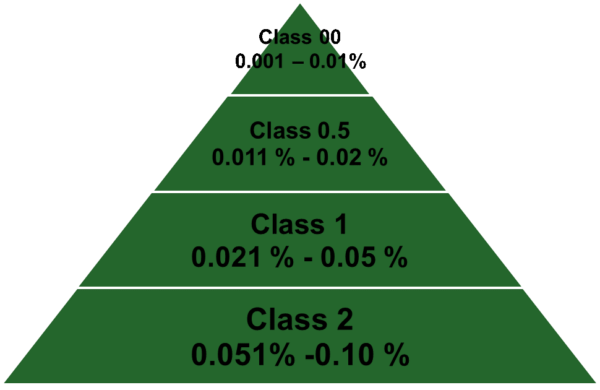
Figure 2 ISO 376 Expanded Uncertainty of Applied Calibration Force
Calculation and Analysis of Data
This section may be the most dramatic regarding differences. ASTM E74 uses the observed data to calculate a standard deviation from the difference in the individual values observed in the calibration and the corresponding values taken from the calibration equation.

The equation uses the differences and divides by a more conservative number by subtracting the number of deflection values minus the degree of polynomial fit minus one. This value is then converted to the proper force unit and multiplied by 2.4. The multiplied value is called the Lower Limit Factor or LLF. A loading range is defined based on certain criteria. If the device was calibrated using deadweight primary standards and is intended to be used to calibrate other force-measuring instruments, then a Class AA loading range can be assigned. The Class AA range is assigned by multiplying the LLF by 2000 assuming the non-zero force point is taken below this value and that the resolution of the force-measuring instrument is less than the LLF.
If the force-measuring device was calibrated using another force-measuring device with a Class AA loading range, then only a Class A loading range can be assigned by substituting 2000 for 400 as the multiplier. ASTM E74 works on the concept that the deadweight primary standards are at least ten times more accurate than the secondary standards with a Class AA loading range. The Class AA standards are five times more accurate than the Class A standards, and the Class A standards are four times more accurate than a one percent testing machine shown in Figure 1 above.
ISO 376 uses the observed values to ensure that certain characteristics of the force-proving instrument are met and rates the device's performance based on its characteristics. ISO 376 uses either four runs of data and a creep test or six runs of data to characterize the force-proving instrument and the associated relative error. ISO 376 then takes the highest error percentage per point for each parameter and assigns a class based on the highest error shown in Figure 3 below. Force-proving instruments where only increasing data is used (four runs of data) are tested for reproducibility, repeatability, resolution, interpolation, zero, and creep.
However, force-proving instruments where increasing and decreasing data is used (six runs of data) are tested for reproducibility, repeatability, resolution, interpolation, zero, and reversibility. The expanded uncertainty of the applied calibration force must also be less than the table allows. If a force-proving instrument has a relative error % for one of the parameters more than what is required for Class 00, but meets the criteria for all other parameters, then the best classification for the device is limited by class for the highest error. ISO 376 classifies everything per point and then breaks down the classification per loading range. If the relative error of reversibility is Class 1, but all other criteria meet Class 00, then the device is rated as a Class 1 device, assuming that the expanded uncertainty of the applied calibration force meets the criteria, as well. What ISO 376 does very well is that it accounts for the uncertainty of the applied calibration force within the standard. A force-proving device cannot have an Uncertainty of less than the reference used for calibration, as shown in Figure 3 above. ASTM E74 addresses this point in the appendix and not in the main body of the standard. ASTM E74 currently allows for a Lower Limit Factor that can be less than the uncertainty of the reference standard. In fact, Euramet cg-4 features a useful write-up on this topic.
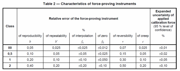
Figure 3 Table 2 from ISO 376 Standard for Classification of Force-Proving Instruments
Eurament cg-4 states in section 6.2 note “ASTM E 74 includes a mandatory method for calculating a value of uncertainty, which it defines as “a statistical estimate of error in forces computed from the calibration equation of a force-measuring instrument when the instrument is calibrated in accordance with this practice.” This calculation of uncertainty only includes contributions due to reproducibility and deviation from the interpolation equation, although the value is increased to equal the resolution if the original value is calculated to be lower, and the uncertainty of the calibration force applied is also specified to be within certain limits. The method results in an uncertainty value, in units of force, which is applicable across the range of calibration forces and is used to determine the lower force limits for the two standard loading ranges (2 000 times the uncertainty for Class AA and 400 times the uncertainty for Class A). The uncertainty calculated by this method ignores some of the components included in Section 6.1 and, as such, is likely to result in different, and probably lower, values. The use of only the calculated uncertainty value associated with the calibration when developing an uncertainty budget for the subsequent use of the force-measuring instrument should be avoided – the contributions due to the other uncertainty components present during the calibration should also be included.
The author suggests reading Euramet cg-4 v 2.0 for more information on Uncertainty of Force Measurements as the goal of this article is to show there is quite a bit of difference between the two standards.
Recalibration dates
ASTM E74-13a in section 11 deals with recalibration intervals. To simplify things, if the force-measuring device demonstrates 0.032 % or better over the Class AA range, or 0.16 % over the Class A range, then a two-year calibration interval can be assigned. 11.2.2 states If this criterion is not demonstrated, then the end Devices not meeting the stability criteria of 11.2.1 Section shall be recalibrated at intervals that shall ensure the stability criteria are not exceeded during the recalibration interval. ISO 376 in section 8.3.2 allows for a maximum validity of the calibration certificate to not exceed 26 months.
Reporting Criteria
ISO 376 requires:
- the identity of all elements of the force-proving instrument and loading fittings and of the calibration machine;
- the mode of force application (tension/compression);
- that the instrument is in accordance with the requirements of preliminary tests;
- the class and the range (or forces) of validity and the loading direction (incremental-only or
- incremental/decremental);
- the date and results of the calibration and, when required, the interpolation equation;
- the temperature at which the calibration was performed;
- the uncertainty of the calibration results (one method of determining the uncertainty is given in Annex C);
- details of the creep measurement, if performed
ASTM E74-13a per section 13 requires:
The report issued by the standardizing laboratory on the calibration of a force-measuring instrument shall be error-free and contain no alteration of dates, data, etc. The report shall contain the following information:
- A statement that the calibration has been performed in accordance with Practice E 74. It is recommended that the calibration be performed in accordance with the latest published issue of Practice E 74.
- Manufacturer and identifying serial numbers of the instrument calibrated,
- Name of the laboratory performing the calibration,
- Date of the calibration,
- Type of reference standard used in the calibration with a statement of the limiting errors or uncertainty,
- The temperature at which the calibration was referenced,
- Listing of the calibration forces applied and the corresponding deflections, including the initial and return zero forces and measured deflections.
- Treatment of zero in determining deflections 8.1(a) or (b), and if method (b) is elected if zero was determined by the average or interpolated method.
- List of the coefficients for any fitted calibration equation and the deviations of the experimental data from the fitted curve,
- Values for the instrument resolution, the uncertainty associated with the calibration results, and the limits of the Class A loading range,
- A statement that the Lower Force Limit expressed in this report applies only when the calibration equation is used to determine the force.
Misc Items
Both ASTM E74 and ISO 376 have non-mandatory appendixes. The ISO 376 appendix deals with bearing pad tests which are highly recommended for verifying that there is no interaction between the force transducer of an instrument used in compression and its support on the calibration machine. Morehouse can perform bearing pad tests if requested. The ASTM E74 appendix does not address adapters which can be a large source of error (see Morehouse blogs on force measurement errors) ISO Annex A 4 discusses loading fittings. Loading fittings should be designed in such a way that the line of force application is not distorted. As a rule, tensile force transducers (shown in Figure 4 below) should be fitted with two ball nuts, two ball cups, and, if necessary, with two intermediate rings, while compressive force transducers should be fitted with one or two compression pads (shown in figure 5 below).

Figure 4 Morehouse Quick Change Tension Adapter Value Kit meets ISO 376 standard annex A.4 requirements.
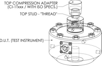
Figure 5 Drawing of Morehouse Load Cell with ISO 376 Compression Adapter
Summary
This article is intended to show that ASTM E74 is not the same as ISO 376; one cannot effectively use an ASTM E74 calibration to certify to ISO 7500, and one cannot effectively use an ISO 376 calibration to certify to ASTM E4. It is possible, however, to use some of the ISO 376 data for analysis with ASTM E74. This practice assumes that the minimum number of test points is met. This article is not comprehensive since several other differences exist between both standards in addition to those discussed here. We recommend purchasing the standards for anyone wanting to perform force calibrations to ASTM E74 or ISO 376. Morehouse can provide calibration to ISO 376, ASTM E74, or both standards. If you need calibration in accordance with either standard, it is important to look at the scope of accreditation and verify that your calibration provider has the capability mentioned on their scope, as shown in Figure 6.
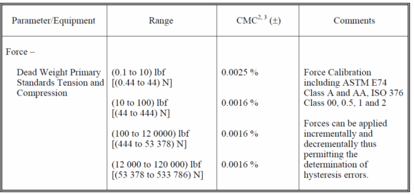
Figure 6 Sample from Morehouse Scope Showing ASTM and ISO 376 Capability
References
[1] ASTM E74-13a is titled Standard Practice of Calibration of Force-Measuring Instruments for Verifying the Force Indication of Testing Machines
[2] ISO 376:2011 Metallic materials — Calibration of force-proving instruments used for the verification of uniaxial testing machines.
[3] EURAMET cg-4 Version 2.0 – Uncertainty of Force Measurements.
If you enjoyed this article, check out our LinkedIn and YouTube channel for more helpful posts and videos.
Everything we do, we believe in changing how people think about force and torque calibration. Morehouse believes in thinking differently about force and torque calibration and equipment. We challenge the "just calibrate it" mentality by educating our customers on what matters and what causes significant errors, and focus on reducing them.
Morehouse makes our products simple to use and user-friendly. And we happen to make great force equipment and provide unparalleled calibration services.
Wanna do business with a company that focuses on what matters most? Email us at info@mhforce.com.


