

What Causes Force Measurement Errors- What Not to Do: Examples of Unsafe or Bad Measurement Practice

Expanded explanations and technical basis from Force Calibration for Technicians and Quality Managers (Zumbrun, 2026)
This is a selection of examples in our new E-book which explains in much greater detail why each pictured setup represents poor force measurement practice. Most large force errors originate from how force is applied (alignment, adapters, contact surfaces, thread engagement, and load path), not from the sensor electronics. These examples can create large measurement errors, reduce repeatability, increase uncertainty, and introduce serious safety hazards.
Reference basis: Zumbrun, Henry A., Force Calibration for Technicians and Quality Managers, 4th edition (2026).
Key topics used throughout: stress/strain fundamentals; compression vs tension setups; loading-condition impacts;
off-center and side-load sensitivity; adapter hardness/flatness; thread engagement; measurement uncertainty and risk.
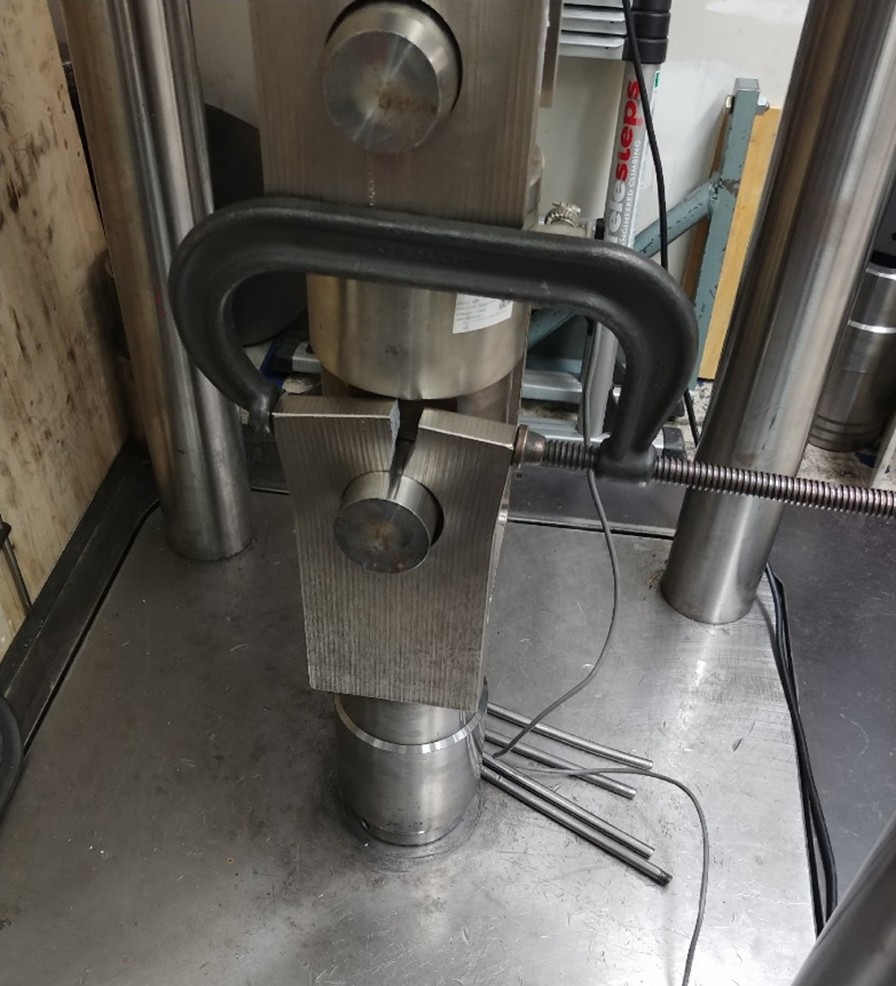
Example 1 - Small pin in a larger hole; cracked clevis with an improvised C-clamp fix (Joking on the fix 😊)
What happened: A small pin was installed in a larger clevis hole. The resulting stress concentration and bending cracked the clevis. A C-clamp was added as an improvised “fix.”
Why this is bad practice:
- A pin-to-hole mismatch shifts load transfer to a small contact area and produces localized high stress (stress increases as effective area decreases).
- The load path is no longer axial; eccentric contact introduces bending and side load components.
Measurement consequences:
- Introduces bending strain that the sensor may interpret as force, causing bias and nonlinearity.
- Creates uncontrolled Type B uncertainty contributors that are not represented in the calibration certificate.
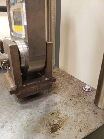
Example 2 - Welded clevis not perpendicular; undersized pin
What happened: A clevis was welded out of square (not perpendicular) and assembled with a pin much smaller than the hole.
Why this is bad practice:
- Non-perpendicular geometry forces the load line off-axis, introducing side loading and torsion.
- Weld distortion and heat-affected zones can change material properties and stiffness.
- Undersized pins repeat the stress concentration and bending problems from Example 1.
Measurement consequences:
- Side load sensitivity can become a dominant error term; readings can shift with small alignment changes.
- Performance metrics such as Non-Linearity and hysteresis can change due to the different stress states. Zero shifts may also occur.
- Results are not reproducible unless the exact geometry and contact conditions are replicated.
Safety consequences:
- Fatigue and fracture risk at the weld and clevis corners.
- Potential for pin shear or clevis tear-out under shock loading.
Bottom line: Out-of-square fixtures convert an axial force measurement into a combined bending/torsion problem, increasing error and hazard.
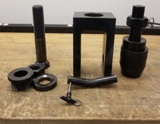
Example 3 - Small pin and large hole (repeat failure mode)
What happened: Another setup where a small pin is used in a larger hole, producing clearance, impact loading, and uneven contact. In addition to the large clearance for the pin, this setup is also wider than it needs to be.
Why this is bad practice:
- Clearance allows rotation and shifting contact points, so the line of force changes during loading.
- Changing contact area changes stress distribution and strain output, violating repeatability conditions.
- Causes extra bending stresses in the pin. The loading capacity of the pin depends on both the diameter and the length between the clevis.
- If loaded off center in a Morehouse UCM or Deadweight Machine, it can create higher stresses on one side of yoke. This can create bending or even breakage. If the pin was strong enough, spacers could be used to center the shackle.
Measurement consequences:
- Expect large run-to-run variability and poor reproducibility, especially if the setup is rebuilt.
- Potential for step changes in output as contact shifts during loading.
Safety consequences:
- Impact loading and sudden shifts can overload fixtures or sensors unexpectedly.
Bottom line: If the force line moves during the test, the measurement is not controlled - and the uncertainty can grow dramatically.
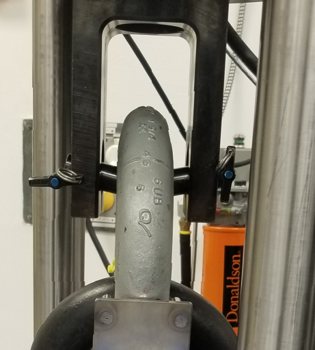
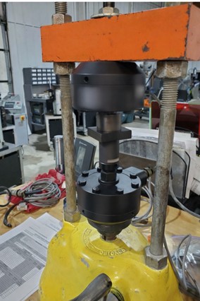
Example 4 - Using a compression device in a tension application (unsafe orientation)
What happened: A compression digital ring force gauge was used in tension. The application appears unstable and unsafe.
Why this is bad practice:
- Compression and tension setups require different adapters and loading paths; many devices are not designed to be pulled in the same way they are compressed.
- Changing loading direction changes the stress state and can invalidate calibration assumptions.
Measurement consequences:
- These devices do not have great symmetry and thus the compression calibration will have different deflection from that of the tension calibration.
Safety consequences:
- Dropped load risk if the device or adapters are not rated for tension.
- Sudden failure can create severe injury risk in line-of-force tension setups.
Bottom line: Do not change the intended loading direction without proper fixtures, ratings, and a calibration that matches the use condition.
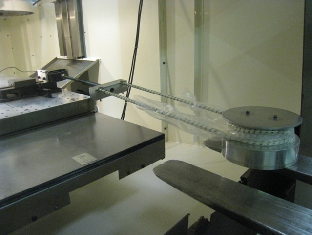
Example 5 - Uneven loading against a surface (UCM loaded flat without proper contact control)
What happened: Several Devices Under Test were loaded against a surface in a way that creates uneven loading and contact.
Why this is bad practice:
- Adapter flatness, hardness, and controlled contact geometry are required to keep loading uniform.
- Non-flat or uneven contact causes stress gradients and off-axis components.
Measurement consequences:
- Increases off-center loading error and can shift output between runs.
Safety consequences:
- Contact damage (brinelling) and sudden slip risk as surfaces seat.
Bottom line: If you cannot control contact surfaces, you cannot control force data - the setup will dominate the result.
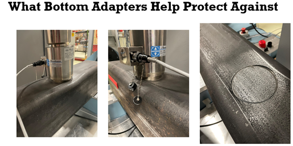
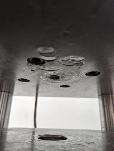
Example 6 - Load cell harder than the material it is loaded against (needs softer sacrificial block)
What happened: A hard load cell was loaded against a softer material, risking damage to the mating surface and changing contact conditions.
Why this is bad practice:
- Soft mating materials can indent under load, changing contact area and load distribution during the test.
- This violates the requirement that loading conditions be stable and repeatable.
Measurement consequences:
- Output can drift as indentation progresses; hysteresis and return-to-zero error increase.
- Repeatability degrades because each loading cycle changes the contact surface.
Safety consequences:
- Surface damage can cause unexpected seating or slip, leading to sudden load shifts.
Bottom line: Use properly designed sacrificial blocks or adapters so contact hardness and flatness remain controlled and repeatable. Typically, the blocks used in calibrating machines will be softer than the load cell and the loading surfaces of the machine. These blocks will likely need to be ground flat prior to using them again. Best practice is to have matching top and bottom blocks for any load cell that is sent in with it for calibration.
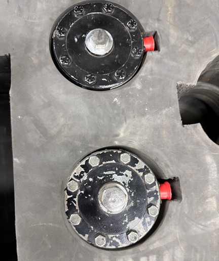
Example 7 - Uncontrolled thread engagement, adapter geometry, and contact surfaces
What happened: Thread engagement, adapter geometry, andontact surfaces are not controlled or repeatable.
Why this is bad practice:
- Thread engagement and bottoming-out can change the load path and strain distribution.
- Different adapters (or the same adapter installed to a different depth/torque) can produce materially different outputs.
Measurement consequences:
- Expect bias shifts and nonlinearity changes when adapters are swapped or installed differently.
- Significant errors (often 0.1 % to 2 % depending on the design and engagement) are possible if calibration conditions are not replicated.
Safety consequences:
- Thread stripping or sudden disengagement risk if engagement is insufficient or mismatched.
Bottom line: If the mechanical interface is not repeatable, your force measurement is not repeatable - and your calibration data will not transfer.
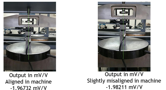
Example 8 - Applied force outside the intended force line (off-axis loading shown)
What happened: Force is applied well away from the intended line of force through the center of the sensing element.
Why this is bad practice:
- Off-axis loading introduces bending moments and cosine error.
- Many sensors have specified off-center and side-load sensitivities that become dominant when misaligned.
Measurement consequences:
- Large indication errors are expected; small misalignments can create outsized measurement bias.
- Rotation or repositioning often yields different results, indicating poor reproducibility.
Safety consequences:
- Bending stresses can overload fixtures and cause sudden failure.
Bottom line: Correct the load path first; do not attempt to “calibrate out” a bad mechanical setup.
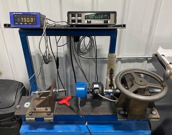
Example 9 - Overhung moment and torsion (errors likely > 0.3 %)
What happened: The setup introduces a clear overhung moment and torsion rather than pure axial load.
Why this is bad practice:
- Force measurement devices are typically calibrated for axial loading. Adding torsion and bending changes the stress state and the sensor output.
- The machine and fixtures must be rigid, plumb, and aligned to minimize extraneous loads.
Measurement consequences:
- Errors greater than 0.3% are plausible; hysteresis and nonlinearity increase.
- Repeatability may look acceptable in one orientation but fail when rebuilt or rotated.
Safety consequences:
- Overhung loads can cause fixture rotation, slip, or sudden release.
Bottom line: Eliminate torsion and bending moments - otherwise the measurement becomes an uncontrolled multi-axis problem.
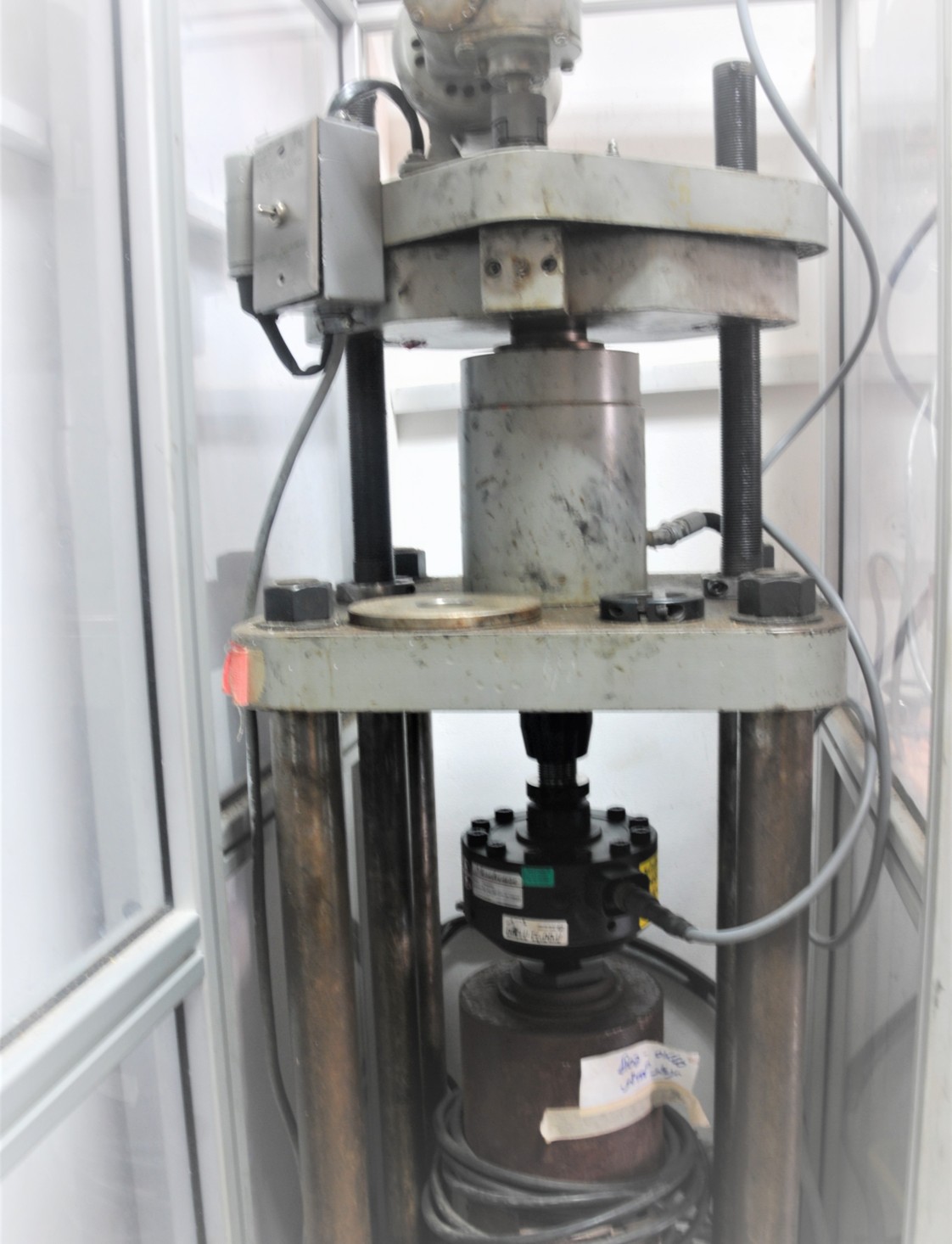
Example 10 - Reference standard placed below the jack (easy to distort the axial line)
What happened: The machine was designed for the reference to be above the jack, but the reference is placed below. The axial load line is easy to distort.
Why this is bad practice:
- Machine configuration affects alignment and rigidity; changing load stack order can introduce angular misalignment and torsion.
- Calibration results are only portable when the use conditions replicate the calibration conditions.
Measurement consequences:
- Increased bias and instability due to shifting load line.
- Greater uncertainty and higher probability of failing comparisons (e.g., PT/ILC) due to non-reproducible loading conditions.
Safety consequences:
- Unstable stack height and side loads increase the chance of buckling or sudden slip.
Bottom line: Use the machine as designed, or treat the alternate configuration as a different method that requires validation and matching calibration conditions.
Example 11 - Failed PT test due to misalignment (not surprising)
What happened: The setup is visibly misaligned throughout, resulting in poor agreement and a failed proficiency test.
Why this is bad practice:
- Measurement accuracy is a combination of trueness (bias) and precision; poor alignment creates systematic bias.
- Higher uncertainty tightens decision limits (guard banding), increasing false failures or false accepts if not handled correctly.
Measurement consequences:
- High between-lab variability and inconsistent results across setups.
- Elevated measurement decision risk when uncertainty is underestimated or ignored.
Safety consequences:
- Misaligned mechanical stacks are more likely to slip, buckle, or fracture under load.
Bottom line: PT/ILC failures are often mechanical, not mathematical - fix alignment, adapters, and loading conditions before blaming the reference standard.
Final technical summary for What Causes Force Measurement Errors
- Large force measurement errors almost always originate in mechanics: alignment, adapters, contact surfaces, thread engagement, and load path.
- Calibration results are only portable when the use setup replicates the calibration conditions (fixtures, adapters, rigidity, and loading direction).
- Off-axis loading introduces bending/torsion that can dominate the signal and create large Type B uncertainty contributors.
- When loading conditions are not controlled, repeatability can appear acceptable while reproducibility collapses (especially after disassembly/rebuild or rotation).
- Unsafe fixtures increase the likelihood of sudden slip, fracture, or dropped loads - treat safety as part of the measurement system.
| Training note (recommended): Review these pictures during onboarding and require technicians to identify:
1) The intended line of force; 2) Where bending/torsion is introduced; 3) What must be controlled to make results repeatable. If the team cannot describe the load path, do not run the test. |
About Morehouse
We believe in changing how people think about Force and Torque calibration in everything we do, including helping others with discovering what causes force measurement errors.
This includes setting expectations and challenging the "just calibrate it" mentality by educating our customers on what matters and what may cause significant errors.
We focus on reducing these errors and making our products simple and user-friendly.
This means your instruments will pass calibration more often and produce more precise measurements, giving you the confidence to focus on your business.
Companies around the globe rely on Morehouse for accuracy and speed.
Our measurement uncertainties are 10-50 times lower than the competition, providing you with more accuracy and precision in force measurement.
We turn around your equipment in 7-10 business days so you can return to work quickly and save money.
When you choose Morehouse, you're not just paying for a calibration service or a load cell.
You're investing in peace of mind, knowing your equipment is calibrated accurately and on time.
Through Great People, Great Leaders, and Great Equipment, we empower organizations to make Better Measurements that enhance quality, reduce risk, and drive innovation.
With over a century of experience, we're committed to raising industry standards, fostering collaboration, helping with understanding risk, and delivering exceptional calibration solutions that build a safer, more accurate future.
Contact Morehouse at info@mhforce.com to learn more about our calibration services and load cell products.
Email us if you ever want to chat or have questions about a blog.
We love talking about this stuff. We have many more topics other than what causes force measurement errors.
Our YouTube channel has videos on various force and torque calibration topics here.
# What Causes Force Measurement Errors

