

Bad Load Cell Setup: Specific Load Cell Examples, Common Errors, and What to Watch for by Load Cell Type
A Bad Load Cell Setup almost never starts with the readout. It starts with the mechanical load path, meaning alignment, adapters, thread engagement, and contact surfaces. When those are not controlled, you introduce off-axis forces such as bending, side load, and torsion, plus unstable contact conditions and inconsistent assembly variables. The result is force errors, poor repeatability, and shifts between calibration and real use.
This article focuses only on load cells, with load cell specific examples and the setup errors that most often cause measurement problems.
What a Bad Load Cell Setup is at a high level
Load cells are designed and calibrated to measure force along a preferred axis, usually axial tension or compression. A setup becomes a Bad Load Cell Setup when the applied force no longer travels through that intended axis consistently.

Most bad load cell setups fall into these buckets.
Off-axis loading
The force is not centered or aligned with the load cell’s intended axis, which creates bending moments and cosine error.
Side loading and torsion
The fixture applies force with a lateral component or twists the load cell stack.
Uncontrolled threaded interfaces
Thread engagement depth is inconsistent, bottoming out occurs, or torque varies. Any of these can change the internal load path.
Unstable contact surfaces
Soft or uneven surfaces indent, slip, or seat during loading, changing the contact area and altering the output.
The key idea is simple. If the mechanical interface is not repeatable, the measurement will not be repeatable.
Some common measurement errors from bad load cell setups

Bias shifts
A small alignment change can cause a large shift in indicated force because the stress state inside the load cell changes.
Note: Misalignment typically occurs between the measuring and applied force vectors.

Nonlinearity and hysteresis changes in bad load cell setups
Off-axis forces and unstable contact conditions can change the apparent nonlinearity and hysteresis because the cell is not loaded the way it was designed or calibrated. Off-axis loading can also alter the slope and span of the load cell.

Poor reproducibility after rotation
A setup may look fine until you rotate a component or swap an adapter. Then readings move because contact points and force lines move.

Drift and return to zero problems
If the load cell is pressed into a softer surface or a surface that seats or creeps, you can see drift during loading and poor return to zero after unloading. Though a poor zero return could also be due to a poor load cell design.
Note: the figure shows an upward drift, though some load cells may have negative creep.
Specific bad load cell setup examples that create bad results
Note: Non-center load should theoretically run lower, not higher, on a good load cell.
Example 1: S-beam load cell with misaligned rigging that creates a side pull (off-axis load)
What it looks like
An S beam load cell is installed with rigging hardware such as clevises, shackles, and pins that does not keep the line of force centered. Clearance in the hardware lets the connection shift under load. The load cell sees a side pull or twisting component.
Why this becomes a Bad Load Cell Setup
S beam load cells are commonly used in tension applications, but they are sensitive to off-axis loading. If rigging allows the force line to wander even slightly, the load cell experiences bending and side load instead of pure axial tension.
Typical measurement problems
Even slight misalignment less than 1/8 inch has been documented to produce a large errors (our example shows 0.752 % error on a 10,000 lbf S-beam), this error caused the expanded uncertainty to increase approximately 9-fold (from roughly 10 lbf to 90 lbf). This is sufficient to cause a technician to adjust a machine that is actually in-tolerance, with potential downstream recall consequences. Repeatability is poor from run to run.
What to watch for
Use hardware that keeps the force line centered and stable. Minimize clearance and uncontrolled rotation at pins. Avoid geometry that allows side pull.

Example 2: S-beam load cell in compression loaded through threads versus loaded flat
What it looks like
The same S-beam load cell is used in compression, but the compression load can be introduced in different ways depending on the adapter and setup. In one configuration, the force is applied through a threaded interface (for example, through the top and bottom threads), which is generally preferred when symmetry error is a concern. Symmetry error is the difference in output between the maximum force in compression and the maximum force in tension.
In other configurations, the load cell may be tightened against the threads or loaded flat-on-flat against a base or platen. The figure above shows the output of the S-beam load cell under these different adapters and loading conditions. In practice, the adapter often changes between calibration and use, even when the load cell itself stays the same.
Why this is a bad setup
Some load cells, especially S-beam designs, can produce different outputs depending on how compression enters the body. Threaded versus flat loading changes the stress distribution through the element and can change the indicated force.
When loaded through the threads in both modes, the S-beam load cell's symmetry is often extremely good. However, flat-on-flat loading is not recommended because the output can vary significantly depending on exactly where and how the force transfers through the contacting materials. Even changes in the interface area at the top or bottom can alter deflection and, therefore, the reading.
Typical measurement problems
The most common issue is that the load cell calibrates one way but reads differently in production when the loading interface changes. This typically shows up as a bias shift and can also appear as a change in nonlinearity.
The worst-case documented in testing is comparing full thread-through loading to flat-on-flat loading, which produced a maximum output difference of 0.369 %. A smaller but still meaningful error, almost 0.03 %, was observed simply from the difference between loading through the threads versus loading flat on the bottom while still threading on top. These are not edge cases; they represent transitions that commonly occur when a load cell is calibrated one way and shipped to a customer who uses it another way.
What to watch for
Calibrate using the same compression interface you will use in the field. Keep adapters consistent and treat them as part of the measurement system. If symmetry error matters, loading through both top and bottom threads is often preferred, but whatever configuration you choose, the key is to avoid switching interfaces between calibration and application.
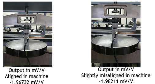
Example 3: Button load cell with off-center loading and a soft contact surface

What it looks like (Bad setup on the left side)
A button load cell is placed between platens for a compression test. The contact point is slightly off center, the platens are not perfectly parallel, or the button is centered by eye instead of being mechanically aligned. At the same time, the button is pressing into a surface that is softer than the load cell or not truly flat, so the contact spot shifts and grows as the force increases.
Why this becomes a Bad Load Cell Setup
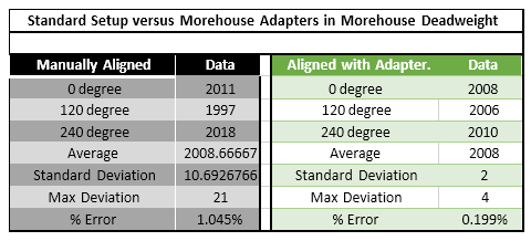
Button load cells have a small contact area and are highly sensitive to how force enters the sensor. A 0.1 % misalignment can produce a large cosine error, and cells calibrated without proper adapters have been documented to show errors from 1 % to 10 % of rated output. In Morehouse testing, using proper button load cell adapters improved reproducibility by 525 % compared to manually aligned setups.
When the load is even slightly off center, the button sees bending and side loading instead of clean axial compression. If the mating surface is soft or seats under load, it can indent and reform the contact patch during the test. That means the load path is changing while you are trying to measure it, which is exactly what drives unstable force readings.
Typical measurement problems
The readings often shift as the setup changes, even if you are holding a constant force. Drift becomes more noticeable during force holds because the surface continues deforming. Hysteresis and return to zero get worse because loading and unloading do not follow the same contact condition. Repeatability suffers when you reposition the button, rotate it, or rebuild the stack, and the scatter usually grows at higher loads, where small alignment errors create bigger bending effects.
What to watch for
Use proper button load cell adapters and alignment features so the force stays centered and consistent. Keep platens flat, parallel, and hard enough that they do not indent under load. Avoid hard on soft contact by using hardened loading blocks or stable interfaces. Treat adapters and contact surfaces as part of the measurement system and keep them consistent between calibration and use.
Example 4: Top block hardness and flatness can change a load cell’s output

What it looks like
A hard load cell is loaded against a softer platen or material. Under load, the surface deforms and the contact patch changes during the test.
Why this is a bad load cell setup
If the mating surface indents or creeps, the load path changes during the measurement. With button and miniature designs, small contact areas make this especially damaging because the setup depends on stable contact conditions.
Typical measurement problems
Our example shows the output can shift by up to approximately 0.3 % when the top pad material or hardness changes. Flatness is a separate and compounding contributor: a non-flat adapter or base has been documented to triple repeatability errors, and a non-flat base can increase rotational error by approximately 5×. Both hardness and flatness must be controlled they are not the same problem. Expanded uncertainty can jump because the adapter becomes the dominant contributor. Repeatability also worsens noticeably when the top block or load cell base is not flat on the ground, and results may vary more between rebuilds or different block configurations.
What to watch for
Use hardened, flat, stable loading blocks or platens. Replace or recondition contact surfaces when they wear or dish. Avoid hard on soft contact when accuracy matters.
Example 5 Shear web or shear beam load cell with inconsistent thread engagement

What it looks like
A shear web load cell is installed using threaded adapters. Thread engagement depth varies between setups. The adapter bottoms out differently or is tightened differently. Sometimes the adapter is omitted when it should be used.
Why this becomes a Bad Load Cell Setup
Even if a load cell is robust to some off axis effects, the threaded interface can dominate the error. Thread engagement changes can shift how the load transfers into the sensing element, changing output. One specific, documented example: if an alignment plug is not seated flush to the base, leaving even one or two threads exposed below the load cell, the load transfers through the internal threads rather than the base, adding approximately 0.012 % calibration error on shear web cells and often damaging the alignment plug. The correct standard is to thread the plug flush to the bottom of the load cell, then one additional turn in, verifying no threads are exposed. This should be inspected visually every time before loading.
Typical measurement problems
Bias shifts when the adapter is installed differently. Differences appear between calibration and use. Results change when swapping adapters even if the load cell is unchanged.
What to watch for
Standardize thread engagement depth and tightening method. Prevent bottoming out. Treat the adapter as part of the system and keep it consistent from calibration to use.
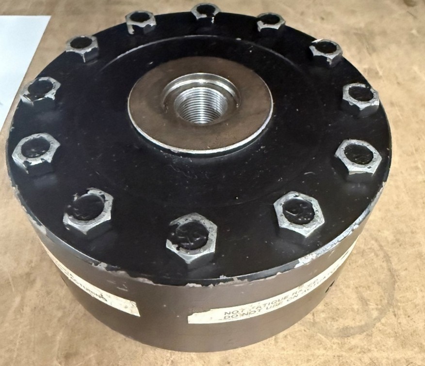
What should your load cell look like

Having the adapter installed is better because it keeps the load cell’s force path controlled and repeatable, which is the whole goal of accurate force measurement.
When the correct adapter is installed, the load is introduced into the load cell the way it was designed to be loaded. That means the contact surface, alignment features, and thread engagement are consistent, so the strain pattern inside the sensing element stays predictable. This reduces off-axis loading, bending moments, and “mystery” stress paths that can change the output even when the applied force is the same.
It also protects you from common setup errors. Without the adapter, it is easier to bottom out threads, vary engagement depth, or load through unintended surfaces. Those small assembly differences can shift the load path and create bias shifts, worse repeatability, and changes in apparent nonlinearity or hysteresis. With the adapter installed, you remove a lot of that variability because the interface is standardized.
Finally, keeping the adapter installed makes calibration more meaningful. If the load cell is calibrated with a specific adapter and then used without it, you are no longer matching the calibration conditions. Using the same adapter in calibration and in the field makes your calibration results transfer more reliably to real measurements.
What else to look out for

In this picture, it is apparent that someone tried to remove the top adapter. If we calibrate the load cell and observe a large shift exceeding expectations, we have good reason to believe the evidence before us indicates that someone removed the adapter. The simple solution is DO NOT DO OR TRY THIS!
Example 6: Shear web load cell loaded through the base versus flat

What it looks like
An alignment plug or threaded alignment feature is installed incorrectly. Threads remain exposed where the plug should be seated.
Why this is a bad setup
When an alignment plug is not seated correctly, the load can be introduced in a way that changes the internal load path or loads through threads in an unintended way. This can create measurable error and can damage components.
Typical measurement problems
Small but real bias errors that are hard to diagnose. Setup to setup differences because assembly is not repeatable.
What to watch for
Use a clear assembly standard for seating depth and inspection. Verify installation visually every time before loading.


Example 7: Torque and Bolting a Load Cell
What it looks like
A load cell that is normally bolted to a base in a test machine is unbolted for calibration or moved between machines, then reinstalled later. The load cell may be bolted down by a different technician, with different bolts, a different base, a different tightening method, or a different torque value. Sometimes the bolts are not tightened in a consistent star or crisscross pattern, and sometimes one or more bolts are not fully torqued. In other cases, the load cell is shipped in without being bolted to its base at all, then mounted at the calibration lab in a way that does not match how it is installed in the field.
Why this becomes a Bad Load Cell Setup
Bolting is part of the force path. Changing the bolting procedure changes how the load transfers through the load cell and into the base, which changes strain distribution and output. Differences in thread class, bolt properties, base material, surface finish, hardness, stiffness, alignment, and flatness all become additional error sources when the load cell is removed and reinstalled. Even if the same torque value is targeted, variability between technicians and tightening methods can be large and hard to quantify. If the calibration is performed with a different mounting condition than the real application, the calibration data may not represent how the load cell actually behaves when it is used.
Typical measurement problems
The most common symptom is a measurable shift from previous calibration results after the load cell is reinstalled. Output can change simply from tightening to a different torque value. In a real calibration example on a 60,000 lbf load cell, changing the bolting torque from 25 lbf ft to 45 lbf ft produced about a 0.7 percent output difference, and the deviations from the fitted curve were much lower when the load cell was bolted properly. Reproducibility can also collapse when bolting is inconsistent. Missing one or two bolts or failing to torque evenly can make performance significantly worse, and errors can be several times higher than expected. These changes often show up as poor repeatability between rebuilds, larger scatter, unexpected nonlinearity, and results that depend on who installed the load cell and how they tightened it.
What to watch for
Bolt the load cell to its base before sending it for calibration, and use the same bolting method you use in the field. Send the actual bolts used to attach it, and send a base that matches the material and flatness of the one used in service whenever possible. Use a consistent tightening sequence, hand-tighten in a crisscross or star pattern, then final torque with a calibrated torque wrench in the same pattern. Make sure every bolt is present and torqued correctly. Missing or unevenly torqued bolts have been documented to produce errors three times the expected performance.
Example 8: Thread Reducer and Thread Depth
What it looks like
A threaded reducer, bushing, or thread adapter is installed in the load cell’s main threaded port so a smaller stud, eye bolt, or fixture can be used. The reducer may sit proud, sit too deep, bottom out early, or have inconsistent engagement from one setup to the next. In some cases it is installed with whatever tool is available, without a clear standard for torque, thread locker, or engagement depth. The reducer can also introduce extra interfaces, meaning more places for looseness, rocking, or misalignment to start.
Why this becomes a Bad Load Cell Setup
A thread reducer changes the way force enters the load cell. Just like varying thread depth, changing engagement depth or bottoming conditions changes the internal load path and can shift the load cell’s output. A reducer also adds a second threaded joint, which increases variability and increases the chance of unintended bending or side load if the load line is not perfectly centered. The bigger issue is safety. A reducer can reduce the effective thread engagement, change the shear area, and create stress concentrations at the interface. The best practice is to avoid thread reducers entirely by using correctly-sized threaded hardware or purpose-built adapters for force measurement. When a reducer cannot be avoided, it must be treated as a controlled measurement component, not a convenience part, and rated for the full load, material, and duty cycle.
Typical measurement problems
You will often see output shifts between setups that look similar on the outside because the reducer seats differently each time. This can show up as poor reproducibility after reinstalling, swapping fixtures, or rebuilding the stack. The load cell may also appear to “change calibration” because the strain pattern changes with engagement depth and seating condition. In addition to measurement error, reducers introduce safety-related failure modes such as backing out under cyclic loading, thread galling or stripping, cracked reducers from over torque, and sudden load release if the reducer or mating stud fails. Even when it does not fail, slight loosening can add movement that increases scatter and makes the system feel unstable.
What to watch for
Use a reducer only when it is rated for the full load, material, and duty cycle, and only when it provides adequate thread engagement for both sides of the joint. Standardize the installation, including engagement depth, torque, and whether thread locking is allowed for that application. Make sure the reducer does not bottom out in a way that changes seating from one build to the next. Inspect threads for wear, galling, and deformation, especially after overloads or cyclic testing. Keep the load line centered and avoid any setup that adds bending or side loading through the reducer. If safety is critical or the loading is dynamic, treat the reducer as a controlled component, not a convenience part, and consider eliminating it by using the correct threaded hardware or a purpose-built adapter designed for force measurement.

Example 9: Cable Length, Gauge, and Configuration Errors
What it looks like
A load cell is calibrated with a specific cable of a fixed length, and the gauge is then returned to service with a different cable. The replacement may be longer, shorter, a different wire gauge, or a different configuration entirely. In other cases, the original cable is damaged and spliced or swapped without recalibration. Sometimes, a 4-wire cable that shipped with the cell is replaced with whatever cable is available in the shop.
Why this becomes a Bad Load Cell Setup
Cable errors fall into two distinct categories that are easy to conflate but have different causes and fixes.
The first is a mechanical error: on smaller load cells in particular, a stiff cable can provide a parallel load path, meaning some of the applied force travels through the cable rather than through the sensing element. This is a setup problem, not an electrical one. The mitigation is to orient the transducer so the live end faces toward where the force is being generated, and to ensure the cable does not create a lateral pull or introduce bending at the connection point.
The second is an electrical error caused by resistance change in 4-wire systems. In a 4-wire cable, the excitation and signal lines share the same conductors. Cable resistance is a function of temperature, and any change in cable length, gauge, or operating temperature causes a voltage drop that directly affects span output. A 4-wire system has no way to compensate for variations in lead resistance.
The sensitivity error from changing a 4-wire cable is quantifiable and significant:
- Approximately 0.37 % per 10 feet of 28-gauge cable
- Approximately 0.09 % per 10 feet of 22-gauge cable
In documented testing, interchanging cables in a 4-wire system produced an error of 0.106 %, and adding that error to the combined uncertainty roughly doubled the uncertainty at mid-range forces compared to the same cell with a 6-wire cable.
Typical measurement problems
Span shifts after cable replacement or repair, without any change to the load cell itself. Temperature-dependent drift in readings that is mistakenly attributed to the load cell or the indicator. Results that differ between the calibration lab (with one cable) and the field (with a different cable). Recalibration appears to fix the problem, but the error returns when the cable is changed again.
What to watch for to prevent a bad load cell setup
For 4-wire systems: treat the cable as part of the calibrated measurement system. Mark each cable with a serial number and keep it paired to the system it was calibrated with. Do not substitute cables of a different length or gauge without recalibrating the complete system. If a cable is damaged and must be replaced, recalibrate immediately after.
The better long-term solution is to move to a 6-wire (sense lead) system. In a 6-wire setup, dedicated sense lines allow the indicator to measure and compensate for the actual voltage at the load cell terminals, eliminating the effect of lead resistance variation. A 6-wire system produces consistent readings regardless of cable length or gauge, and is particularly important for long cable runs or environments where temperature changes significantly.
If you are currently using a 4-wire system in a fixed installation where the cable never changes, the error is systematic and will be absorbed into calibration. The risk is when the cable is changed, and the system is not recalibrated.
Load cell types and set up risks with what to watch for
S-beam load cells
High risk includes side pull, twisting, and changing rigging geometry. Watch for a centered force line, stable pin and clevis connections, and consistent compression interface.
Button and miniature load cells
High risk includes off-center contact, dependence on surface condition, and rotation sensitivity. Watch for alignment features, hardened flat parallel platens, and a stable contact patch. Errors of 1 % to 10 % of rated output without proper adapters; proper adapters can improve reproducibility by 525 %
Shear web
High risk includes threaded interface errors, adapter omission, and inconsistent engagement length. Watch for controlled engagement depth, no bottoming out, and consistent adapters. Misalignment error is much lower (Our examples document the error at 0.0022 % versus 0.75 % for S-beams under comparable conditions). Loading through the bottom threads versus on the base is a consistent error of 0.01 – 0.012 %, while varying the thread depth can be 10x that or greater.
Column load cells
High risk includes off-center loading, overhung moment, and inconsistent top adapters. Watch for centering, a rigid short stack, and consistent adapter material and geometry.
Bad Load Cell Setup checklist before you test
Stop and fix the mechanics first if any of these are true.
- The force line is not clearly centered and axial through the load cell
- There is clearance or geometry that allows the load to walk under force
- You are using different adapters than the ones used during calibration
- Thread engagement depth or tightening method is not controlled
- The load cell contacts a softer surface that can indent or seat during loading
- The stack is tall, flexible, or overhung and likely introduces bending or torsion
- The adapter or contact surface is not flat, worn, or dished
- The bolts are missing, unevenly torqued, or tightened in a different sequence than during calibration
- The load cell requires bolting and was calibrated unbolted, or bolted to a different torque value than used in the field
- The torque wrench used to mount the load cell has not been verified for accuracy
- An alignment plug is installed but not seated correctly — any threads visible below the base of the load cell mean the load is transferring through the internal threads, not the base
- The loading interface changed between calibration and use — for example, thread-loaded during calibration but flat-on-flat in the field, or vice versa
- A thread reducer or thread adapter is in use without a controlled standard for engagement depth and torque
- The cable has been replaced, extended, or changed to a different gauge since the last calibration and the system uses a 4-wire configuration
- The cable is stiff enough on a smaller load cell that it may be providing a parallel load path and carrying part of the applied force
Practical takeaway
A Bad Load Cell Setup is a mechanical problem before it is a measurement problem. The best accuracy improvement is usually a repeatable axial load path with controlled interfaces and stable contact surfaces.
About Morehouse
We believe in changing how people think about Force and Torque calibration in everything we do, including, "Bad Load Cell Setup: Specific Load Cell Examples, Common Errors, and What to Watch for by Load Cell Type."
This includes setting expectations and challenging the "just calibrate it" mentality by educating our customers on what matters and what may cause significant errors.
We focus on reducing these errors and making our products simple and user-friendly.
This means your instruments will pass calibration more often and produce more precise measurements, giving you the confidence to focus on your business.
Companies around the globe rely on Morehouse for accuracy and speed.
Our measurement uncertainties are 10-50 times lower than the competition, providing you with more accuracy and precision in force measurement.
We turn around your equipment in 7-10 business days so you can return to work quickly and save money.
When you choose Morehouse, you're not just paying for a calibration service or a load cell.
You're investing in peace of mind, knowing your equipment is calibrated accurately and on time.
Through Great People, Great Leaders, and Great Equipment, we empower organizations to make Better Measurements that enhance quality, reduce risk, and drive innovation.
With over a century of experience, we're committed to raising industry standards, fostering collaboration, helping with understanding risk, and delivering exceptional calibration solutions that build a safer, more accurate future.
Contact Morehouse at info@mhforce.com to learn more about our calibration services and load cell products.
Email us if you ever want to chat or have questions about a blog.
We love talking about this stuff. We have many more topics other than, "Bad Load Cell Setup: Specific Load Cell Examples, Common Errors, and What to Watch for by Load Cell Type."
Our YouTube channel has videos on various force and torque calibration topics here.
# Bad load cell setup

