

A Load Cell Is a Spring You Learn to Trust: A Guide to Strain Gauge Load Cells
A load cell is a precision spring: a strain gauge load cell converts the elastic element's deformation under force into an electrical signal through bonded strain gauges and a Wheatstone bridge. Non-linearity, hysteresis, and creep all describe how far that signal drifts from the ideal straight line.
I saw a LinkedIn post the other day about measuring a spring to ensure the electrical signal accurately represents the mechanical reality. When I saw this, I thought, wow, this is a pretty cool analogy, and I could add a whole lot more and make this a training piece about load cells using a spring. Thus the inspiration for this article was born.
What Can a Simple Spring Teach us about Precision Measurement?
More than you might think.
A spring follows one of the most fundamental equations in engineering:

Force creates displacement, in direct proportion. Squeeze an egg in your hand, and it breaks at a known force, and it takes the same force in Pennsylvania as it does in Peru. Force is force. Newton told us in his second law that force controls motion, so if we want to control motion, we must control force.
Here is the pivot: every load cell you have ever used is a spring. A very good spring, machined from steel or aluminum, designed to deform elastically and predictably, with strain gauges bonded to it so we can read that deformation electrically. Once you see a load cell as a calibrated spring, the whole specification sheet starts to make sense.
From Force to Strain:
When a force acts on a body, the body deforms. Stress is force per unit area:

Strain is the fractional change in length:

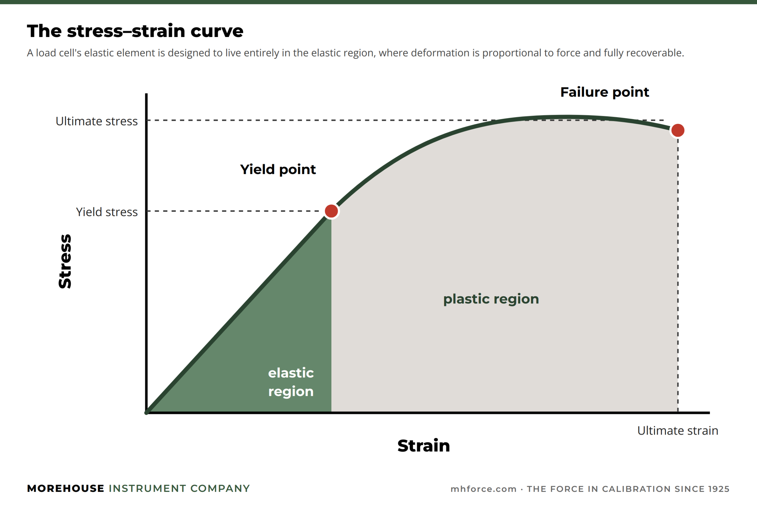
If the elastic element stays within its elastic limit, Young's modulus tells us the column will shorten in compression or lengthen in tension by an amount directly proportional to the force applied. That proportionality is the entire basis of the load cell. Push past the yield point into the plastic region and the deformation becomes permanent; push far enough, and the material fails. A load cell's elastic element is designed to live entirely in the elastic region.
There is a second effect worth knowing. Poisson's ratio predicts that when a column shortens under compression, its diameter increases; under tension, the diameter decreases. A strain gauge bonded along the axis and a strain gauge bonded around the circumference will change resistance in opposite directions for the same force, and the circumferential gauge will see roughly one-third the resistance change of the axial gauge. Load cell designers use both.

From Strain to Signal
Before load cells, force measurement meant mechanical direct-reading devices such as proving rings. Morehouse built a 3 000 kgf analog proving ring in 1926, and we still build digital versions today. Rings work, but a proving ring is not a temperature-compensated device, and the operator must correct for temperature, preload, and tare. Try doing that while measuring the thrust of a jet engine. Proving rings have logistical challenges that load cells do not.
The strain gauge changed everything. A bonded foil strain gauge is a grid of foil on a thin backing, bonded tightly to the elastic element. When the element strains, the foil strains with it. The foil's length and cross-sectional area change, and its resistance changes with them. Compression shortens the grid and decreases resistance; tension stretches it and increases resistance.
If we can precisely measure that resistance change, we can compute the force.
That is where the Wheatstone bridge comes in. Four strain gauges (typically two in tension and two in compression) form the bridge arms. Excite the bridge with a known voltage, and the output, expressed in mV/V, is proportional to the force applied. The load cell combines the response properties of strain gauges with the elastic properties of a physical member. A spring you can read remotely.
The accuracy of that signal depends on more than the strain gauges themselves. Most load cells use four active gauges, a full bridge, so no completion resistors are required; completion resistors belong to quarter- and half-bridge strain measurements, which are rare in load cells. But every load cell bridge circuit still contains other resistive elements: zero-balance resistors and temperature compensation resistors trimmed into the network. Those must remain stable as temperature, load, and time change. Otherwise, the output may reflect resistor drift rather than the behavior of the spring, which is why high-stability foil resistors are used for compensation in precision load cells.
When measuring a spring, the goal is not just to calculate force. It is to ensure the electrical signal accurately represents the mechanical reality.

What the specification sheet is really telling you
Every load cell specification sheet describes how far the spring departs from ideal. Three to five terms do most of the work; I like repeatability and reproducibility as well, though few specification sheets include them.
- Non-linearity – output error against the straight line between minimum and maximum load
- Hysteresis – output difference at the same force point depending on approach direction
- Non-repeatability – scatter across repeated loadings; the one error calibration cannot correct
- Creep – output drift over time under constant load
- Static error band – non-linearity and hysteresis combined into a single envelope
Non-linearity is the algebraic difference between the output at a specific load and the corresponding point on the straight line drawn between minimum and maximum load, usually expressed in % of full scale and usually largest between 40 % and 60 % of capacity.
Here is a worked example. A load cell reads 0 mV/V at 0 lbf, 1.20002 mV/V at 600 lbf, and 2.00010 mV/V at 1 000 lbf.



That is 0.002 % of full scale at the 600 lbf point.
Non-linearity matters most when your indicator only has a two-point span, captured at zero and capacity. If your indicator supports multiple span points and you use coefficients from an ASTM E74 or ISO 376 calibration, the non-linear behavior can be corrected and the error significantly reduced.
Hysteresis is the difference in output at the same force point depending on whether the force was approached increasing or decreasing. The spring remembers where it has been.
Non-repeatability is the scatter in output when the same force is applied the same way, multiple times.
Creep is the change in output over time under constant load. Springs relax.
Static error band wraps non-linearity and hysteresis into a single envelope around the best-fit line.
When broken out individually, these terms help you select a suitable load cell for the application and tell you which errors calibration can correct, and which cannot. If the specification also lists non-repeatability or references the ISO 376 Class or ASTM E74 llf, then you have a more accurate picture of how well the load cell will perform.

Note: We do realize some specification sheets read like Nigel Tufnel's amplifier in This Is Spinal Tap. 'These go to eleven,' sure. An extra digit on a datasheet is only meaningful if the measurement process behind it can support it; otherwise, it's likely marketing fluff.
Not all Springs are Built Alike
An S-beam load cell can be ideal for measuring small forces (under 50 lbf) when physical weights cannot be used, and it is well suited to scales and tension applications. It is also susceptible to off-axis loading, and its compression output will differ if it is loaded through the threads versus flat against the base. It is typically not the right choice for calibrations to ASTM E74, ASTM E4, ISO 376, or ISO 7500.
Morehouse offers smaller low-capacity load cells at 50 and 25 lbf if you need small cells. HBM makes some very good small load cells in their Burster series, if space is minimal. Shear web and column designs behave differently again. The pattern that matters: every load cell type has loading conditions under which it performs, and loading conditions under which it lies to you. Replicating how the instrument was calibrated is essential to getting proper force measurements from it.
The Mechanical Reality: Alignment and Adapters
Equipment used to measure force should be made to minimize off-center loading, bending, and torsion. Force machines need to be plumb, level, square, rigid, and free of torsion. If the loading surface bends, alignment errors follow, and the results do, too.
How much can misalignment cost?
We tested a spherical adapter without an alignment plug. With less than 1/8 in of misalignment, the observed error on an S-beam load cell was 0.752 %. When the load cell was aligned and appropriately calibrated, the expanded uncertainty was approximately 10 lbf (k = 2, approximately 95 % confidence). Misaligned, it was approximately 90 lbf. On a 10 000 lbf S-beam load cell, that is the difference between a measurement and a guess.
Think through the consequences. A technician misaligns a load cell in a testing machine and adjusts a machine that was actually in tolerance. A recall may result from that simple error. Alignment plugs and base plates with alignment holes can drastically reduce misalignment errors. We have observed errors as high as 2 % of full-scale output from varying loading conditions and adapters alone.
The load cell did not fail. The spring did exactly what a spring does. The setup changed the mechanical reality, and the electrical signal faithfully reported it.

When the Spring is a Cable
Here is a case where the spring is not inside the instrument at all. A cable tensiometer measures the tension in a cable, wire, or rope, and the cable itself is the elastic element. Everything we said about springs applies, and the calibration problems that follow are a perfect illustration of why loading conditions matter.
For a uniform member in tension, elongation follows e = F·L/(A·E). Rearranging gives the spring rate:

Spring rate rises with cross-sectional area and material stiffness and falls with length. A shorter cable is a stiffer spring. That is why cable length is a leading error source in tensiometer calibration: manufacturers often recommend cables of 3 ft or greater, and labs using 18 in to 24 in cables will likely see larger differences, with the biggest gaps at the lower test points. Stranded aircraft cable adds torsion and bending on top of the simple model, but the same principles hold.
The calibration method matters even more. There are two common approaches.
Method 1: clamp and adjust. Load the cable near the target, clamp the tensiometer, then adjust the force back to nominal: load to 460 lbf, clamp, read 495 lbf, adjust back to 500 lbf. Adjusting after the clamp manually compensates for the tension the tensiometer introduces, so the results approach a deadweight machine with one fixed point.
Method 2: clamp at force. Apply 500 lbf, clamp, and read. The value can jump to 528 lbf because clamping shortens the effective cable length between two fixed points, and the stiff cable-spring answers with more tension. This method better represents real-world field use, where that clamp-induced tension is present in every measurement.
Different calibration methods can produce discrepancies of over 20 %. Cable type moves the numbers too: a 3/32 in galvanized aircraft cable (GAC) and a 3/32 in stainless steel aircraft cable (SSAC) read differently on the same tensiometer, enough that a unit can fail its ±8 lb specification on one cable type and pass on the other. The tensiometer manufacturer confirms it: SSAC requires a different calibration than GAC.
So which method is right? The one that replicates how the end user works. Are they clamping a tensioned cable, or adjusting tension based on the calibration chart? If the calibration laboratory never asks, the certificate can be internally perfect and operationally wrong. On an aircraft, that is a rudder that does not feel right to the pilot.
The tensiometer did not change. The load cell reference did not change. The spring did what springs do, and the method decided which spring we were measuring.

The Takeaway
A load cell is a spring with a nervous system. Hooke's law governs the deformation, the strain gauge translates it, the Wheatstone bridge reports it, and everything that impacts the mechanical performance, like various adapters, determines whether the number on your indicator represents the force in the machine. That is the whole job of a strain gauge load cell: making sure the spring, the signal, and the setup agree.
If you calibrate or use load cells, pull one of your specification sheets this week and work through it term by term: non-linearity, hysteresis, non-repeatability, creep. Then look at your adapters and ask whether your loading conditions replicate how the instrument was calibrated. That one review can be worth more than a tighter tolerance.
If you want help selecting the right load cell or the right adapters for your application, reach out. This is what we do all day.
And yes, we call ourselves the Galaxy's #1 Force and Torque Lab, because “world class” and all the other outrageous marketing claims were already taken. At Morehouse, we like to have fun and take measurements seriously. The marketing fluff, not so much.
-Henry Zumbrun, Morehouse Instrument Company
About Morehouse
We believe in changing how people think about Force and Torque calibration in everything we do, including, "A Load Cell Is a Spring You Learn to Trust: A Guide to Strain Gauge Load Cells"
This includes setting expectations and challenging the "just calibrate it" mentality by educating our customers on what matters and what may cause significant errors.
We focus on reducing these errors and making our products simple and user-friendly.
This means your instruments will pass calibration more often and produce more precise measurements, giving you the confidence to focus on your business.
Companies around the globe rely on Morehouse for accuracy and speed.
Our measurement uncertainties are 10-50 times lower than the competition, providing you with more accuracy and precision in force measurement.
We turn around your equipment in 7-10 business days so you can return to work quickly and save money.
When you choose Morehouse, you're not just paying for a calibration service or a load cell.
You're investing in peace of mind, knowing your equipment is calibrated accurately and on time.
Through Great People, Great Leaders, and Great Equipment, we empower organizations to make Better Measurements that enhance quality, reduce risk, and drive innovation.
With over a century of experience, we're committed to raising industry standards, fostering collaboration, helping with understanding risk, and delivering exceptional calibration solutions that build a safer, more accurate future.
Contact Morehouse at info@mhforce.com to learn more about our calibration services and load cell products.
Email us if you ever want to chat or have questions about a blog.
We love talking about this stuff. We have many more topics other than, "A Load Cell Is a Spring You Learn to Trust: A Guide to Strain Gauge Load Cells"
Our YouTube channel has videos on various force and torque calibration topics here.