

Torque Transducer Bending Error on Single-ended Arms: CW CCW Torque Test
Torque transducer bending error can be one of the most underestimated contributors in single-ended-arm torque calibration. If you calibrate torque transducers on a single-ended arm and you have not characterized the bending error, your uncertainty budget may be significantly off. In our worked example on a 1 000 N·m setup, the arm by itself biased the indicated torque by 0.169 %. That is nearly three times the Class AA limit in ASTM E2428-22, Standard Practice for Calibration and Verification of Elastic Torque Measurement Standards. The bias was easy to miss on the raw calibration data. This post explains what overhung load is, why a single-ended arm can make torque transducer bending error dominant, and the clockwise/counter-clockwise (CW/CCW) test you can run on almost any torsion cell to quantify it.
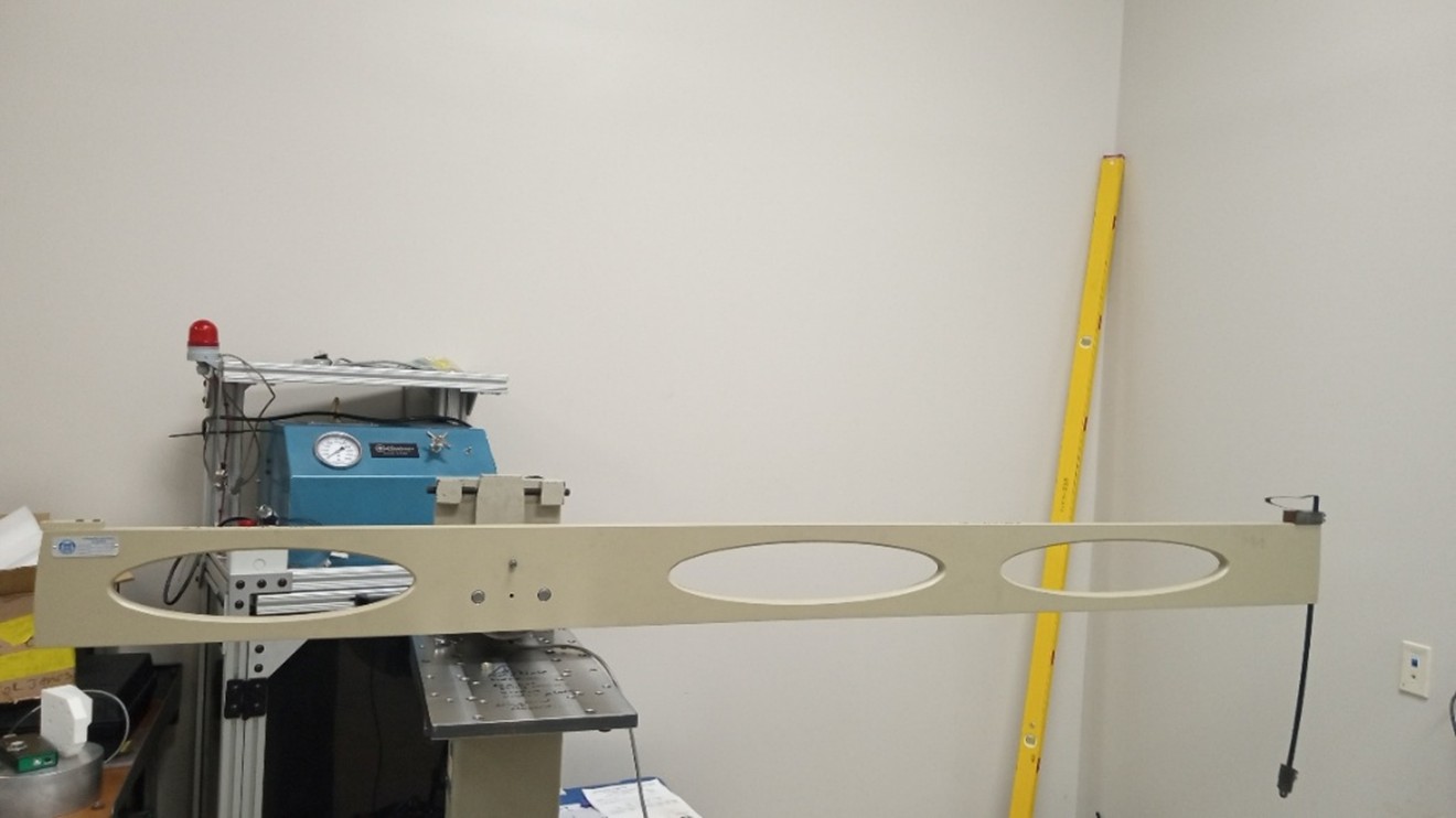
A single-ended torque arm installed on the transducer in a field calibration frame. The arm carries weight on one side only; its own mass loads the transducer before the first calibration weight is added.
Where torque transducer bending error comes from
A torque calibration certificate is only valid if the transducer sees a pure torsional input. In a single-ended arm setup, one weight stack hangs on one side of the transducer. There is no counterweight and no bearing. The transducer never sees a pure torsional input. The arm has mass. That mass acts at a center of gravity offset from the transducer’s measurement plane. The result is a vertical side load on the transducer and an overturning moment about its measurement plane. Both are present before you hang the first calibration weight.
Real torque transducers respond to this off-axis loading. Not by design. The strain-gage bridge is intended to reject bending. No real bridge is perfectly balanced. Gauge placement, element machining, and adhesive bonding all carry small tolerances, and the residual leaks a fraction of any bending load into the torque reading. The transducer indicates this leakage as torque error.
A few numbers fix the scale of the problem. A 1.524 m (5 ft) single-ended arm weighing 156 N (35 lbf) imposes a side load of 156 N and an overturning moment on the order of 119 N·m (87.5 lbf·ft) on the transducer at zero applied torque. ASTM E2428 caps the expanded uncertainty of a Class AA secondary torque standard at 0.06 % and of a Class A reference at 0.25 % of indication at the lower torque limit. A moderate single-ended arm on a bending-sensitive cell can produce a torque transducer bending error comparable to or larger than these limits. The error does not scale with applied torque. It stays roughly constant. As a percentage of indication it grows hyperbolically toward zero. The bottom of your verified range is where it does its worst damage.
The 2007 UK torque intercomparison (Robinson and Knott, 2009) made this concrete across ten laboratories. For the 100 N·m transducer in that round-robin, orientation-dependent output variation from bending sensitivity exceeded the other uncertainty components. Deviations of several tenths of a percent at the low end of the range were common. The effect is not just theoretical.
What overhung load is
Overhung load is any load on the elastic element of a torque transducer whose vector is not aligned with the intended torque-measurement axis. In a single-ended arm, two components dominate:
- Side load: the weight of the arm plus the deadweights acting vertically through the loaded center of gravity.
- Overturning moment: that side load multiplied by the distance from the transducer’s measurement plane to the loaded center of gravity.
ASTM E2428 uses the terms “bending/overturning moments” and “parasitic forces due to misalignment” rather than “overhung load,” but the phenomena are the same. BS 7882:2008 treats them under the same heading. We use overhung load throughout this post.
A single-ended arm has one specific complication that a symmetrical (dual-ended) arm does not: the loaded center of gravity moves as you add weights. The arm alone has one center of gravity; arm-plus-half-load has another; arm-plus-full-load has a third. The overturning moment changes with applied torque rather than staying constant. This is why the standards single out single-ended arms in §X4.8.1 as posing “challenges in quantifying bending/overturning moments that should not be ignored.”
Why a torque transducer responds to bending
Inside a strain-gage torque transducer, four gauges sit on the elastic element at ±45° to the torque axis. Under pure torsion, the four gauges see alternating tensile and compressive strains that all add constructively at the bridge output. That sum is the signal the indicator reports as torque. Under pure bending, two gauges see tension and two see compression, and the contributions cancel at the bridge output. That cancellation is what makes a torque transducer reject bending in the first place.
The cancellation is rarely perfect in practice. Each gauge is bonded with a small angular tolerance. The elastic element has small asymmetries from machining. The four adhesive bonds vary slightly in stiffness. Under bending, the four gauge outputs no longer cancel exactly, and a small residual leaks through. Baumgarten et al. (2019) showed that an angular deviation of only 0.01° in one strain-gauge placement can produce a relative signal change of over 20 % in the parasitic-axial bridge of a 2 kN·m transducer under a 2 000 N·m torque. Manufacturing tolerances of that order are normal for strain-gauge bonding.
Two consequences follow. First, bending sensitivity varies between individual transducers, even within the same model. Shaft-style square-drive cells generally show the lowest bending rejection; web-style (flange) cells can be largely insensitive across most of the working range. Multi-axis transducers measure the extraneous components directly. Second, the manufacturer’s certificate almost never reports the residual. If you want to know what your specific transducer does on your specific fixture, you have to measure it.
The CW/CCW comparison: a test for torque transducer bending error
The double-loading test in ASTM E2428 §X4.7.2 is the preferred quantitative test for bending. It requires a symmetrical arm loaded at both ends simultaneously. You cannot run it on a single-ended arm. The standard acknowledges this gap and points to §X4.3, which covers proficiency testing rather than a quantitative method. The CW/CCW comparison described below is the substitute method, and it applies to nearly every torsion cell mounted on a single-ended arm.
The principle is simple. Install the arm with the loading position clockwise of the transducer axis, and record the output at zero load. Rotate the entire arm to the counter-clockwise position. Same arm, same weight, same geometry, opposite side of the transducer. Record the output again. The torque component reverses sign between the two readings. The bending component, which depends on the direction of the side load, also reverses sign. The difference between the two readings isolates the bending contribution from everything else.
![]()
CW (right), CCW (center), and connector-down baseline (left) mounting of the single-ended arm on the torque cell. The shift between CW and CCW readings, with no calibration weights applied, isolates the bending contribution from the arm’s side load.
The five-step procedure
- Confirm rigid mounting first. A worn square drive or a loose coupling will transmit an off-axis contact force whose direction shifts unpredictably under load. The CW/CCW comparison will measure that slop rather than your transducer’s bending sensitivity. Torque every bolted joint to the manufacturer’s specification with a calibrated torque wrench, verify minimal play in any square drive, and seat all adapters firmly. ASTM E2428 §X4.6.8 is explicit on this point.
- Record the zero-load output with the arm in the clockwise loading position. No calibration weights. Connector orientation fixed. Record the indication in mV/V.
- Rotate the arm to the counter-clockwise loading position. Same arm, same connector orientation, opposite side of the transducer. Record the indication in mV/V.
- Compute the side-load-induced shift. Take the magnitudes of the arm-induced output shifts in each direction (CW reading minus the no-arm baseline, CCW reading minus the no-arm baseline) and subtract them. The result is the bias in the zero-torque reading caused by reversing the side load. Divide that bias by the arm weight to get the transducer’s bending sensitivity coefficient in mV/V per unit force, for this transducer in this fixture.
- Project to full scale. Multiply the per-force coefficient by the total weight that will hang from the arm at full-scale calibration torque. Convert the result to a percentage of the transducer’s nominal full-scale output. That percentage is your estimate of the worst-case bending contribution at full scale, and it goes into the uncertainty budget as a Type B component.
![]()
Why step 1 matters: a good-fit square drive transfers a clean torsional input (left); a worn drive contacts at one corner and transmits torque plus a parasitic bending moment (right) that no subsequent characterization can correct. Confirm rigid mounting before running the CW/CCW test.
A worked number
On a 1 000 N·m Basic Torsion Cell mounted in a Morehouse AKO frame, with a 156 N (35 lbf) arm at 1.522 m (4.993 067 ft), we measured:
- CW zero-load reading: −0.144 48 mV/V
- CCW zero-load reading: −0.148 72 mV/V
- Side-load-induced shift: 0.000 58 mV/V
- Bending sensitivity: ≈ −0.000 016 6 mV/V per lbf
![]()
Four-step projection of the CW/CCW bending estimate to full-scale applied torque. The per-lbf bending sensitivity from the zero-load comparison is scaled by the full-scale calibration weight and expressed as a percentage of nominal output.
Projected to a full-scale weight of 658 N (148 lbf) at 1 000 N·m, the bending contribution was −0.003 46 mV/V. That is about 0.179 % of the nominal full-scale output of 1.931 21 mV/V. For this transducer in this fixture, that one contributor alone exceeds the Class AA limit of 0.06 % and is comparable to the Class A limit of 0.25 % at the lower torque end.
When we calibrated the same cell against the Morehouse primary torque deadweight standard (U = 0.003 %, k = 2), the raw difference was 0.169 % of the primary reading. Applying the CW/CCW-derived correction closed the gap to 0.010 %. That is a factor of seventeen lower. The 0.169 % disagreement was not a transducer defect or an installation mistake. It was bending, and the CW/CCW test found it.
What the result is good for, and what it is not
The CW/CCW estimate is a defensible magnitude for the bending line of your uncertainty budget. Take the projected full-scale shift, divide by √3 for a rectangular-distribution treatment per JCGM 100:2008 §4.3.7, and enter the result as the Type B input on the bending row. ASTM E2428 §6.5 then handles the orientation-dependent component through rotational randomization across four orientations (90° apart for square-drive standards per §6.5.6).
The CW/CCW result is not a correction to apply uniformly across all calibration runs. The bending shift is position-dependent. It changes sign as the arm rotates. Applying the CW/CCW correction at every orientation would subtract the right number at one position and add an equal error at the opposite position. The correction is a budget input, not a calibration adjustment.
The coefficient is also specific to one transducer in one fixture. It does not transfer between cells, and it does not transfer between mounting geometries. Each new transducer that enters service on a single-ended arm should be characterized on its own.
What to do with the result
If the CW/CCW-projected bending contribution lands inside your target uncertainty budget, your single-ended setup is defensible. A Class A calibration on a stiff web-style cell that rejects bending well is a common case. Enter the bending estimate as a Type B contributor, randomize per §6.5, and proceed.
If the projected contribution dominates the budget and pushes you out of compliance, the answer is mechanical, not statistical. Three options exist, in the order Morehouse recommends evaluating them:
- Switch to a less bending-sensitive transducer. A web-style cell can produce roughly four times better bending rejection than a shaft-style square-drive cell of the same capacity. In the worked example above, swapping the Basic Torsion Cell for the AKO-specified web-style cell drops the expanded uncertainty from 0.201 % to 0.055 %. That crosses the Class A threshold.
- Support the arm with a bearing per ASTM E2428 §X4.6.2. The bearing decouples the arm weight from the transducer entirely. The bending contribution becomes zero and is replaced by bearing friction, which on a well-designed bearing is typically smaller and easier to budget.
- Move to a different architecture. A torque transfer (comparison) machine avoids the moment-arm geometry altogether. A dual-radius symmetrical arm carries balanced masses on both sides of the transducer axis. Both eliminate the per-transducer bending characterization step.
![]()
Mechanical isolation of the transducer from the arm weight. Supporting the arm with a bearing eliminates the bending contribution entirely and replaces it with a generally smaller bearing-friction component that must be characterized.
The CW/CCW comparison is a defensible tool for an existing single-ended rig that cannot be re-fixtured. It is not a reason to build a new one.
The takeaway
Torque transducer bending error on a single-ended arm is real, it is measurable, and it can be easy to miss on raw calibration data. ASTM E2428 acknowledges the problem but does not specify a quantitative method for single-ended geometries. The CW/CCW comparison helps fill that gap. Five steps, two readings, one arithmetic projection. You have a defensible Type B input for the bending line of your uncertainty budget. If you are calibrating torque on a single-ended arm and you have not run this test, you may not know what your uncertainty actually is.
References
ASTM E2428-22, Standard Practice for Calibration and Verification of Elastic Torque Measurement Standards. ASTM International, West Conshohocken, PA, 2022.
BS 7882:2008, Method for Calibration and Classification of Torque Measuring Devices. British Standards Institution, London, 2008.
JCGM 100:2008, Evaluation of Measurement Data — Guide to the Expression of Uncertainty in Measurement (GUM). Bureau International des Poids et Mesures, 2008.
Robinson, A. and Knott, A., “UK Torque Intercomparison — 2007,” XIX IMEKO World Congress, Lisbon, September 2009.
Baumgarten, S., Röske, D., et al., “Parasitic loads in torque standard machines: a characterisation, comparison, and evaluation,” Acta IMEKO, Vol. 8, No. 3, pp. 78 to 89, September 2019.
Thompson, A. and Taylor, B. N., Guide for the Use of the International System of Units (SI), NIST Special Publication 811, 2008 Edition. NIST, Gaithersburg, MD, 2008.
Want to read our full paper on torque transducer bending error?
About Morehouse
We believe in changing how people think about Force and Torque calibration in everything we do, including, "Torque Transducer Bending Errors."
This includes setting expectations and challenging the "just calibrate it" mentality by educating our customers on what matters and what may cause significant errors.
We focus on reducing these errors and making our products simple and user-friendly.
This means your instruments will pass calibration more often and produce more precise measurements, giving you the confidence to focus on your business.
Companies around the globe rely on Morehouse for accuracy and speed.
Our measurement uncertainties are 10-50 times lower than the competition, providing you with more accuracy and precision in force measurement.
We turn around your equipment in 7-10 business days so you can return to work quickly and save money.
When you choose Morehouse, you're not just paying for a calibration service or a load cell.
You're investing in peace of mind, knowing your equipment is calibrated accurately and on time.
Through Great People, Great Leaders, and Great Equipment, we empower organizations to make Better Measurements that enhance quality, reduce risk, and drive innovation.
With over a century of experience, we're committed to raising industry standards, fostering collaboration, helping with understanding risk, and delivering exceptional calibration solutions that build a safer, more accurate future.
Contact Morehouse at info@mhforce.com to learn more about our calibration services and load cell products.
Email us if you ever want to chat or have questions about a blog.
We love talking about this stuff. We have many more topics other than, "Torque Transducer Bending Errors."
Our YouTube channel has videos on various force and torque calibration topics here.

