

How to Calibrate Tension Links and Load Shackles: It is all About the Pin When it Comes to Tension Link Calibration
A tension link is calibrated on its pins, not on its label. Two links stamped with nominally the same capacity can behave completely differently under load because they were built around different pins, and if the calibration uses the wrong pin, the certificate is fiction for the link as it is actually used.
That single fact governs tension link calibration and load shackle calibration more than any other. Get the pin right and the rest of the setup is routine. Get the pin wrong and no amount of care elsewhere will save the number.
Why the pin dominates the budget
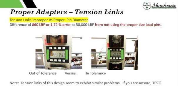
Here is the example that makes people stop and check their own procedures. A 20-ton tension link is often built around a 2.000 in pin. A 25-ton link from another maker uses a 50 mm pin, which is 1.969 in. That is a difference of only 0.031 in. It sounds like nothing.
It is not nothing. That 0.031 in difference consumes roughly 70 % of a 0.1 % full-scale specification on its own, before any other error source enters the budget. The pin changes where and how the load bears inside the link's eye, and the link's output follows the bearing condition, not the number stamped on the side.
So the pin is not an accessory to the calibration. It is a variable in the measurement, and it is the largest one.
The rule that keeps the certificate honest
Always calibrate a tension link or a load shackle with the pin the customer uses in the field. Same diameter, same shoulder, same orientation. You are not calibrating a link in the abstract; you are calibrating the link-and-pin system that will do the lifting.
When the field pin is not available, do not guess and do not quietly substitute the nearest pin on the shelf. Document the calibration pin's diameter and orientation on the certificate so the end user can correct for the difference. A documented pin the user can account for is worth far more than an undocumented pin that silently biases every reading.
Build the tension setup
A tension link or shackle is calibrated in tension, in line with the reference standard. On a Morehouse UCM the load string runs: tension member to clevis to the instrument to clevis to tension member, mirrored top and bottom, with the reference load cell in the same string. The tension member self-aligns the load onto the axis; the clevises carry the link on its pins the way a real lift would.
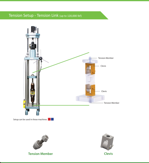
Tension setup for a tension link: tension member to clevis to the instrument to clevis to tension member.
A safety note on welded clevises
The photo below is a real setup, and it fails three checks at once. The clevis is welded rather than machined, and it does not sit perpendicular to the loading axis, so the link is pulled off-square before any force is applied. The material around the pin hole shows possible yielding, indicating the fixture has likely already been loaded beyond what it can carry. And the pin is too small for the link's eye, so the load rides on a narrow line of contact instead of the bearing surface the link was designed around.
Any one of these faults biases the reading. Together, they are a safety problem, not just a measurement problem. A fixture that has yielded does not announce when it will let go; it lets go under load, with the whole string in tension. Ask three questions of every fixture before you load it: Is the clevis square to the load? Has the material deformed? Does the pin fill the eye? If a welded fixture fails any of them, retire it. No reading is worth standing next to hardware that is already telling you it has been overloaded.
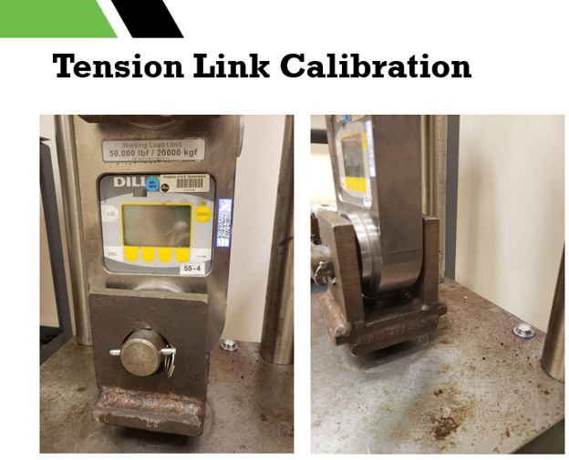
A welded clevis fixture in service: the clevis is not perpendicular to the loading axis, the material around the weld shows yielding, and the pin is too small for the link's eye.
Tension link safety checks
Beyond the fixture itself, the setup has to pass a safety check before any force goes on. The rules are short, and none of them are optional:
- Insert the clevis pin fully, and if the design includes safety pins, install them before loading.
- Use the manufacturer's recommended pin diameter. A pin smaller than recommended can cause failure; the pin question is a safety rule before it is an accuracy rule.
- Check the hole geometry. A noncylindrical hole or large chamfers reduce the contact area on the pin, which lowers the maximum load the link can safely carry.
- Center the link in the clevis, and verify the pin sticks out both sides. Off-center loading can overload one side of the clevis or the machine's yoke.
- Never load a fixture without traceability to its load rating, and reduce that rating any time the setup does not match the fixture's original design intent.
The small-pin, large-hole combination deserves its own warning because it fails in two ways at once. The clearance lets the pin rotate and the contact points shift, so the line of force moves during loading and the reading moves with it. The pin also sees bending stress it was not sized for; pin capacity depends on the diameter and on the length between the clevises, and a loose fit under shock loading can shear the pin or tear out the clevis. If the force line moves during the test, neither the measurement nor the hardware is under control.
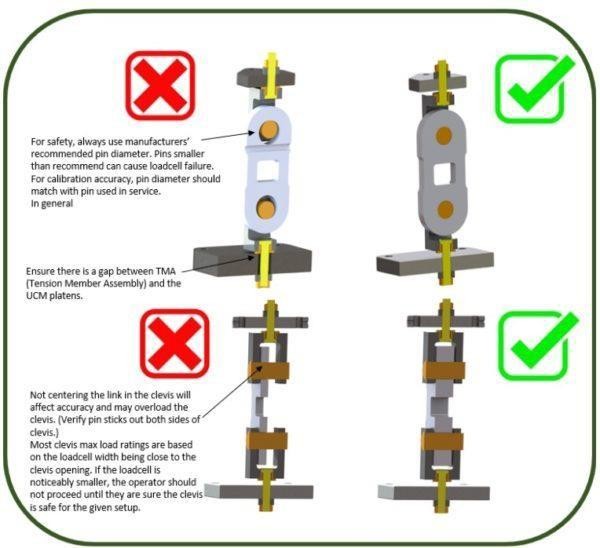
Safety checks in the machine: use the manufacturer's recommended pin diameter, keep a gap between the tension member assembly and the platens, and center the link in the clevis with the pin protruding on both sides.
Proper adapters for tension links
The proper hardware answers the pin question before it is asked. The Morehouse Adaptable Clevis Value Kit (U.S. Patent No. 11,078,052) pairs one set of clevises with multiple pins of different diameters, each machined to the diameter the instrument's manufacturer specifies. The clevises stay in the load string; only the pin changes. Changeover between a dynamometer, a crane scale, and a tension link is a pin swap, not a new setup, and the reading errors that come from inconsistent pin sizes never enter the budget.
The details carry the performance. Precision manufacturing holds the levelness, the alignment, and the specified pin diameters. Protective rollers shield the pins from the concentrated loading a shackle applies. A rust-resistant black oxide coating protects every part. Kits are available in 120 000 lbf (534 kN), 60 000 lbf (267 kN), 30 000 lbf (133 kN), and 12 000 lbf (53.4 kN) capacities, and they work with the Morehouse Quick-Change Tension Members and Adapters for better alignment and easier setup. One kit replaces a shelf of single-purpose clevises, which shows up as real savings in adapter cost, storage space, and process time.
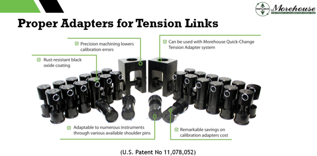
The patented Adaptable Clevis Value Kit: one set of clevises plus pins machined to each manufacturer's specified diameter, with protective rollers for pins under concentrated shackle loading.
Choose the right clevis and pin
The clevis assembly is where the pin question gets answered in hardware. A Morehouse clevis attaches to the tension member through the retaining ring, after the coupling nut is removed, or through an intermediate threaded adapter. A set of two clevises plus pins calibrates many instruments across a wide capacity range.
The pin options matter:
- The TP straight pin is the standard pin for most capacities, from a 10 000 lbf (44.5 kN) clevis up through 1 000 000 lbf (4.45 MN) heavy-pin assemblies.
- The TUZ shoulder-pin assembly, used with a TY bushing, generates smaller pin diameters when the instrument calls for them.
Match the clevis capacity to the link, then match the pin diameter to the field pin. For the largest links the pin variants are specified at the time of order, because at 1 000 000 lbf the pin geometry is doing serious structural work.
Clevis assemblies: clevis, straight pin, shoulder-pin assembly, bushing, and roller.
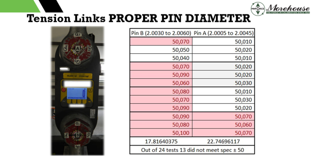
Repeatability data for a 55,000 lbf (25 000 kgf) tension link loaded to a nominal 50,000 on two pins that differ by only a few thousandths of an inch: Pin B (2.0030 in to 2.0060 in) and Pin A (2.0005 in to 2.0045 in). Shaded readings fall outside the ± 50 tolerance; 13 of 24 tests did not meet specification. The slightest pin diameter change is the difference between passing and failing.
Run the calibration
With the link on the correct pin and the string square, the procedure follows standard force practice:
- Exercise the link. Apply full-capacity load two or three times before recording, to settle the structure and the pin bearing.
- Keep the load axial. Let the tension member and clevis pins self-center; do not force the link square by hand.
- Calibrate across the used range. Take readings in even increments to capacity, in the loading direction the link sees in service.
- Record against the reference at each point and note the pin used.
Report the pin, the uncertainty, and the rule
A tension link certificate that does not name the pin is incomplete, because the reader cannot reproduce the measurement. State the pin diameter and orientation. Report the expanded uncertainty with its coverage factor and coverage probability, for example U = 0.11 %, k = 2, approximately 95 % confidence. If you issue a conformity statement, give the decision rule and whether uncertainty was considered. The end user is making lifting decisions on this number, so the certificate has to tell them exactly what they are trusting.
Tension link and load shackle calibration is not complicated, but it is unforgiving about one thing. The pin is the measurement. Calibrate on the field pin, document it when you cannot, and let the tension member and clevises keep the load on axis. Do that and the certificate describes the link the rigger actually uses. If you need clevises and pins matched to your links and shackles, or you are not sure which pin your calibration should use, talk to us before you load anything.
Learn more about our clevis kits here.
About Morehouse
We believe in changing how people think about Force and Torque calibration in everything we do, including, "How to Calibrate Tension Links and Load Shackles: It is all About the Pin When it Comes to Tension Link Calibration"
This includes setting expectations and challenging the "just calibrate it" mentality by educating our customers on what matters and what may cause significant errors.
We focus on reducing these errors and making our products simple and user-friendly.
This means your instruments will pass calibration more often and produce more precise measurements, giving you the confidence to focus on your business.
Companies around the globe rely on Morehouse for accuracy and speed.
Our measurement uncertainties are 10-50 times lower than the competition, providing you with more accuracy and precision in force measurement.
We turn around your equipment in 7-10 business days so you can return to work quickly and save money.
When you choose Morehouse, you're not just paying for a calibration service or a load cell.
You're investing in peace of mind, knowing your equipment is calibrated accurately and on time.
Through Great People, Great Leaders, and Great Equipment, we empower organizations to make Better Measurements that enhance quality, reduce risk, and drive innovation.
With over a century of experience, we're committed to raising industry standards, fostering collaboration, helping with understanding risk, and delivering exceptional calibration solutions that build a safer, more accurate future.
Contact Morehouse at info@mhforce.com to learn more about our calibration services and load cell products.
Email us if you ever want to chat or have questions about a blog.
We love talking about this stuff. We have many more topics other than, "How to Calibrate Tension Links and Load Shackles: It is all About the Pin When it Comes to Tension Link Calibration"
Our YouTube channel has videos on various force and torque calibration topics here.

