

Load Cell Wiring – How do I Know How My Load Cell is Wired?
Numerous load cells exist where the manufacturers have merged, ceased to exist, or do not share their wiring information. This is where we aim to help you figure out the load cell wiring of whatever load cell you have.
Load cell cables generally come in two configurations: four-wire and six-wire. Both types include positive and negative signal lines and positive and negative excitation lines. However, six-wire cables also feature positive and negative sense lines. These sense lines connect to the system’s indicator, either directly or via a junction box, enabling the indicator to detect the actual voltage at the load cell for improved accuracy and compensation of voltage drops in the cable.
1. Do a Web Search or Contact the Manufacturer
The first step in trying to find the load cell wiring of what you need to calibrate or wire is always to search for the manufacturer and model number in hopes of finding the correct wiring. If that fails, calling the manufacturer if they are still in existence will likely yield a positive response. If all else fails, we have some tips to help you find the correct wiring.
2. Check for Standard Color Codes
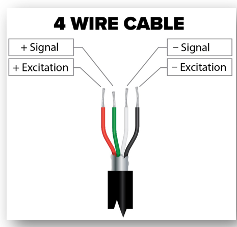
Load Cell Wiring - Wire Colors
Most load cells follow common wiring standards. Try these typical color codes first:
- Excitation+ (E+) / V+: Red
- Excitation- (E-) / V-: Black or Green
- Signal+ (S+): Green
- Signal- (S-): White
- Shield / Ground: Bare or Yellow
However, some manufacturers may use different colors.
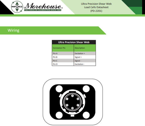
Load Cell Wiring Troubleshooting Example of Morehouse Load Cell Pinout
3. If there are not Wires (Only a Pinned Connector)
The Most Common Wiring is Called Western Regional Where:
- A is (E+) / V+
- B is + (S+)
- C is - (S-)
- D is (E-) / V-
4. Look for Labels or Engravings (If only it were always so easy)
- Check the load cell itself or any terminal connections for printed labels.
- Some load cells have a sticker with wiring information.
5. Use a Multimeter to Identify Pairs (mV/V, non-amplified load cells only)
If no diagram is available, you can use a multimeter to check resistances and identify the correct wires:
- Measure resistance between different wires.
- Excitation (+) and (-) should show a resistance typically between 350Ω and 1,000Ω(for strain gauge load cells). (This is usually done by reading the resistance between all possible combinations. If pair largest resistance pair is 10-200 ohms higher than the second largest pair, it is likely the excitation connections. If there is less than 5 ohms difference between the two highest pairs, it may not be possible to determine the intended excitation unless there are also “sense” leads as noted below. This is usually the second highest resistance pair as determined on previous line)
- If you see infinite resistance, those wires are not directly connected.
Note: There could be a third pair that is sense. If this is the case, the sense wires are shorted to the excitation and the multimeter can be used to find which wire goes where. If you read all the resistance pairs previously, these will be the ones that appear to be a direct short. Or I like to put the multimeter in diode mode and wait till it beeps at me. Say we have 6 pins and Pin A, and Pin E cause the meter to beep, they are connected and we know A and E are ± Excitation. On 6-wire load cells, the pins that are connected/shorted together are always excitation.
Load Cell Wiring Troubleshooting Example:
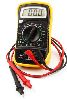
Load Cell Wiring - A handheld multimeter is a great tool to help figure out wiring
Readings were obtained using a handheld multimeter set to Ω
Troubleshooting a 4-wire load cell
Using a multimeter and pin out each of the four pins, A, B, C,&D.
Pin A to Pin B = 263.2Ω
Pin A to Pin C = 262.9Ω
Pin A to Pin D = 350.4Ω
Pin B to Pin C = 350.2Ω
Pin B to Pin D = 263.1Ω
Pin C to Pin D = 262.9Ω
From obtaining these measurements we know that Pin A to D & Pin B to C are our matched pairs. One will be excitation, and one will be signal. Likely Pin A and Pin D are exciting. Though we may need to continue by wiring the cell and making sure the span matches.
Troubleshooting a 6-wire load cell
Pin A to Pin B = 349.0 Ω
Pin A to Pin C = 272.0 Ω
Pin A to Pin D = 272.0 Ω
Pin A to Pin E = 272.0 Ω
Pin A to Pin F = 271.8 Ω
Pin B to Pin C = 272.0 Ω
Pin B to Pin D = 272.0 Ω
Pin B to Pin E = 272.0 Ω
Pin B to Pin F = 272.0 Ω
Pin C to Pin D = 374.0 Ω
Pin C to Pin E = 0.006 Ω
Pin C to Pin F = 374.0 Ω
Pin D to Pin E = 374.0 Ω
Pin D to Pin F = 0.01 Ω
Pin E to Pin F = 373.2 Ω
Excitation pair: Pin C &D (Highest Pair)
Signal Pair: Pin A & B (second Highest Pair)
Sense Leads: F & E
Note: It is arbitrary, in this example, whether we chose C&D to be excitation or chose F&E, we should always document how it was tested so the end user can set it up the same way. If you are a calibration lab, it is worth noting this on the calibration certificate.
Perform Tests While Loading (that may help verify load cell wiring)
- If excitation and signal are wired properly the load cell will be close to the span as known from say a previous calibration or markings on loadcell. This is likely 2 mV/V, 3 mV/V, or 4 mV/V.
- If they are not wired properly, meaning excitation and signal are crossed, the span will likely be 20 – 30 % higher, meaning 2 mV/V becomes 2.4 mV/V or more. (This may seem backward, but if there is a noticeable difference in output, the lower output wiring is usually the correct one. If the difference is slight, determining the intended wiring may not be possible.)
Load Cell Wiring Conclusion
Determining the wiring of an unknown load cell can be challenging, especially when manufacturer documentation is unavailable. However, you can confidently identify the correct wiring configuration by following a systematic approach—starting with a web search or manufacturer inquiry, referencing standard color codes, and using multimeter resistance measurements.
Recognizing excitation, signal, and sense lines is crucial for accurate measurements when working with four-wire and six-wire load cells. If uncertainty remains, performing tests under load can help verify correct wiring by ensuring expected output values. Proper documentation of your findings, particularly for calibration labs, is essential to maintain consistency and repeatable results.
Following these steps, you can successfully wire and troubleshoot most load cells, ensuring reliable performance in measurement applications.
More Information about Morehouse
We believe in changing how people think about Force and Torque calibration in everything we do.
This includes setting expectations and challenging the "just calibrate it" mentality by educating our customers on what matters and what may cause significant errors.
We focus on reducing these errors and making our products simple and user-friendly.
This means your instruments will pass calibration more often and produce more precise measurements, giving you the confidence to focus on your business.
Companies around the globe rely on Morehouse for accuracy and speed.
Our measurement uncertainties are 10-50 times lower than the competition, providing you with more accuracy and precision in force measurement.
We turn around your equipment in 7-10 business days so you can return to work quickly and save money.
When you choose Morehouse, you're not just paying for a calibration service or a load cell.
You're investing in peace of mind, knowing your equipment is calibrated accurately and on time.
Through Great People, Great Leaders, and Great Equipment, we empower organizations to make Better Measurements that enhance quality, reduce risk, and drive innovation.
With over a century of experience, we're committed to raising industry standards, fostering collaboration, and delivering exceptional calibration solutions that build a safer, more accurate future.
Contact Morehouse at info@mhforce.com to learn more about our calibration services and load cell products.
Email us if you ever want to chat or have questions about a blog.
We love talking about this stuff. We have many more topics other than expressing SI units!
Our YouTube channel has videos on various force and torque calibration topics here.

