

Guidance on Uncertainty Budgets for Force Measuring Devices Part 3. Calculating Uncertainty for Force Measuring Devices for Measurement or
Calculating Uncertainty for Force Measuring Devices Background:
Currently, there are discrepancies regarding what is acceptable for a force calibration uncertainty budget. A common mistake is to include too many lines from the load cell specification sheet.
For example, if a load cell is used to make ascending measurements only, the effect of the uncertainty contribution for hysteresis should not be included in the uncertainty budget. Many then have problems with what type of distribution to use as if what is reported is found on the manufacturer’s specification sheet; they may assume Type B.
However, it should be argued that Non-Linearity and Hysteresis determined during calibration are independent of one another and follow a normal distribution making them type A.
Not understanding the load cell specification sheet is another error source. When the specification sheet says units of RO, this is a percentage of Rated Output of the load cell. The percentage of RO is linear throughout the range, meaning 0.02 % of Rated Output at the instrument's capacity is 0.2 % at 10 % of the range.
This section will provide guidance for a commercial calibration which would be a device that is not calibrated to a published standard.
The Author’s ViewPoint:
This author highly recommends that anyone using force-measuring devices to calibrate other force-measuring devices follow the ASTM E74 or ISO 376 standard, as a commercial calibration is not good enough to quantify the expected performance of the load cell.
However, people chose to ignore this statement and insist on using these limited calibrations to disseminate the unit of force further. If one wants not to use an adequate calibration, then at least there is some form of guidance document available. In my opinion, this is an industry problem and those in the industry should remedy the problem by following a published standard such as ASTM E74 or ISO 376.
Note: Morehouse has created an Excel spreadsheet to help labs calculate their CMCs. This Excel sheet can be downloaded @ http://www.mhforce.com/Files/Support/249/CMC-CALCULATIONS-FOR-FORCE-MEASUREMENTS.xlsx
Definitions:
Best Existing Device - is defined as a device to be calibrated that is commercially or otherwise available for customers, even if it has a special performance (stability) or has a long history of calibration. For force calibrations, this is often a very stable load cell and indicator with enough resolution to observe differences in repeatability conditions.
Commercial Calibration – This is usually a 5-6-point calibration done by the manufacturer to verify the device is within specification. It is a calibration that determines if the device is fit for use. It is not a suitable calibration to further disseminate the unit of force and should not be used to calibrate other force-measuring devices.
Deadweight force standard machines – See Primary Standard. Reference Euramet cg-4 for uncertainty contributors and guidance on calculating uncertainties for deadweight force machines.
Environmental Factors – Environmental conditions that influence the load cell output. The most common specification is temperature compensation found on the force measuring devices specification sheet. It is important to note that any deviation in environmental conditions from the temperature the device was calibrated needs to be accounted for.
Example: The calibration lab calibrated a force-measuring device at 23 degrees Celsius. The device is then used from 13 degrees to 33 degrees or ±10 degree Celsius from the calibration. This additional error source could change the output by about 0.015 percent reading per °C, or 0.15 percent for ±10°C.
Force Units – A force unit can be any unit representing a force. Common force units are N, kgf, lbf.
Hysteresis – The algebraic difference between output at a given load descending from the maximum load and output at the same load ascending from the minimum load. Typically expressed in units of % Full Scale. It is most commonly calculated at 40-60 % of full scale.
ISO 376 - Calibration of force-proving instruments used for the verification of uniaxial testing machines. ISO 376 is an International Standard that specifies a method for the calibration of force-proving instruments used for the static verification of uniaxial testing machines (e.g., tension/compression testing machines) and describes a procedure for the classification of these instruments.
Non-Linearity – The algebraic difference between the output at a specific load and the corresponding point on the straight line drawn between the outputs at minimum load and maximum load. Normally expressed in units of % of Full Scale. It is most commonly calculated at 40-60 % of full scale.
Non-Repeatability – The maximum difference between output readings for repeated loadings under identical loading and environmental conditions. Normally expressed in units as a % of Rated Output.
Rated Output or RO – The output corresponding to capacity, equal to the algebraic difference between the signal at minimal load + capacity and the signal at minimum load.
Reference Standard Calibration Uncertainty – This is usually the CMC of the reference standard used to calibrate the force-measuring device. It is the uncertainty of the calibration of the force-measuring device. The repeatability study done for the CMC can be removed if new repeatability with the unit currently being calibrated is conducted.
Reference Standard Stability – The change in output from one calibration to another. This number is found by comparing multiple calibrations against one another over time. If the instrument is new, the suggestion is to contact the manufacturer for stability estimation on similar instruments.
Repeatability – Repeatability is defined as the standard deviation of a series of at least two measurements at the same test point. The purpose of this test is the determination of the uncertainty of force generation in a force-calibrating machine or test frame. For laboratories testing multiple ranges, it is recommended that a repeatability point is taken for every ten percent of the ranges they calibrate. An example would be a lab performing calibrations from 10 N through 10,000 N. The ranges calibrated may be 10 N - 100 N, 100 N - 1,000 N, and 1,000 N - 10,000 N. The recommended practice would be to take test points at 10, 20, 30, 40, 50, 60, 70, 80, 90, 100, 200, 300, 400, 500, 600, 700, 800, 900, 1,000, 2,000, 3,000, 4,000, 5,000, 6,000, 7,000, 8,000, 9,000, and 10,000 N. Note: For this application, zero should never be considered as a first test point. A force-measuring device should not be used to calibrate other devices outside the range it was calibrated over. Example. A device calibrated from 10 % through 100 % of its range should not be capable of calibrating devices outside of this range.
Repeatability and Reproducibility Between Technicians – Repeatability between technicians is found by taking the square root of the averages of the same test point taken multiple times. Reproducibility between technicians is found by taking the standard deviation of the averages of the same test point taken multiple times.
Resolution – Smallest change in a quantity being measured that causes a perceptible change in the corresponding indication.
Reproducibility – Measurement precision under reproducibility conditions of measurement. To figure out the reproducibility of the measurement, it is recommended that each technician performs a test on the same device by taking repeated measurements at the same test point. Reproducibility is found by taking the standard deviation of the average of each of the repeated measurements.
Significant Errors – Those error sources which contribute to at least 5 % of the overall uncertainty budget when summed together. Most force-measuring devices are susceptible to misalignment errors, errors from not exercising the device to full capacity, and errors from improper adapter use. In almost all cases, there will be additional errors if the end-user fails to have the force-measuring device calibrated with the same adapters being used in their application.
Static Error Band - The band of maximum deviations of the ascending and descending calibration points from a best-fit line through zero output. It includes the effects of nonlinearity, hysteresis, and non-return to minimum load. Normally expressed in units of % FS. Note: If the force measuring device is used to make Ascending and Descending measurements and the ending zero is not reduced after use, SEB may be used instead of using Non-Linearity and Hysteresis in calculating CMC. SEB is particularly useful for those who have indicators with only one span point as they can use the SEB number to get an approximation of how far out what they are measuring in the range could be. It is very useful in monitoring forces in various applications.
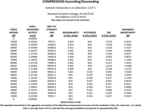
Data from a commercial-type calibration. Morehouse was contracted to perform this calibration, and instead of the typical 5-6-point calibration, we use a 21-point calibration with ascending and descending test points and report both Non-Linearity and Hysteresis. This gives the end-user more data points to fit a curve better, but it still does not tell one the true expected performance of the device.
The end-user could use the maximum SEB value if using the device for verification of a machine, actuator, or another system where both ascending and descending measurements need to be made. Otherwise, the end-user may wish to run two separate CMCs. One for verifying ascending measurements and a separate one for descending measurements.
Uncertainty Example for Devices Not Calibrated to a Published Standard where Non-Linearity, Hysteresis, or Static Error Band may be reported.
These are usually 5-6-point calibrations done by the manufacturer to verify the device is within specification. It is a calibration that determines if the device is fit for use.
Note: If further dissemination of force is required ASTM E74 or ISO 376 should be followed. The intent of the commercial calibration is to verify the manufacturer’s specifications only. It is not intended as a calibration to disseminate the unit of force. Only to prove the load cell is fit for use. If a laboratory chooses to define its procedure, the force-measuring device should be tested for all applicable contributors below.
Type A Uncertainty Contributors
Non-Linearity, Hysteresis, Non-Repeatability, or SEB (Use as type A if and only if there is data to support these)
Repeatability or Non-Repeatability of the Reference Standard.
Repeatability of the Best Existing Device
Repeatability and Reproducibility
Type B Uncertainty Contributors
Resolution of the Best Existing Device
Reference Standard Resolution* If Applicable
Reference Standard Uncertainty
Reference Standard Stability
Environmental Factors
Non-Repeatability
Other Error Sources
Specified Tolerance * If Not Listed and making ascending measurements only. If making Ascending and Descending Measurements and using a Use Static Error Band (SEB) or a combination of Non-Linearity, Hysteresis, and Return to Zero. If the force-measuring device is calibrated with an indicator and set up to have a tolerance, then it may not be necessary to include Non-Linearity or SEB.
*Note: if the device is going to be used at points different from the points it was calibrated at then SEB, Non-Linearity, or Hysteresis may need to be used. It is up to the end-user to validate if they have a significant amount of data to interpolate between test points. A 5-point calibration may not give enough data points to safely interpolate between points. It is generally accepted that a point taken at every 10 % increment may yield good enough results for interpolation.
Hysteresis * (Only if the Device is Used to Measure Decreasing Forces and SEB was not used)
Note: If derived from the manufacturer's specification sheet and not from actual calibration then these may be considered type B. If based on actual calibration data non-linearity, hysteresis, and SEB tend to follow a normal distribution and should be treated as type A. The following example uses Non-Linearity and is based on observed values and is treated as Type A from the values above.
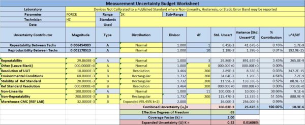
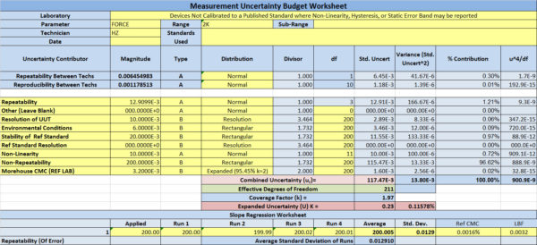
Table 2 Example of a Single Point Uncertainty Analysis for a 2,000 FORCE UNITS Force Device with Not Calibrated to a Published Standard. In This Example, Only Non-Linearity Was Included in The Uncertainty Budget.
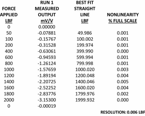
Data to Support Table 2
In this example, the device supplied had a capacity of 2,000 Force Units, and an indicator was supplied. The customer wanted to use the device throughout the loading range and to make both ascending and descending measurements. Therefore, contributions from Non-Linearity and Hysteresis were used.
The calibration was done by taking readings at 50.100,200,400,600,800,1000,1200,1400,1600,1800, and 2000 Force Units, and only one reading was taken at each force point. Again, this may not be sufficient to further disseminate the unit of force as the expected performance of the device cannot be known with just one observation of each applied force.
The recommended practice would be to randomize the loading conditions and perform at least three observations at each test point or follow the ASTM E74 or ISO 376 standard.
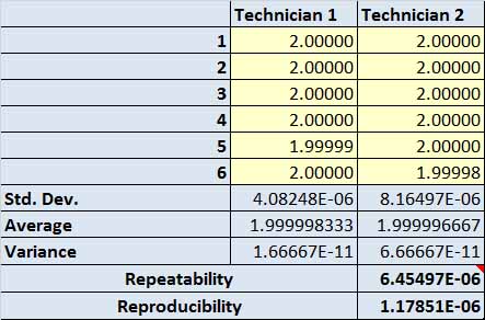
Repeatability and Reproducibility between Technicians - Repeatability and Reproducibility between technicians – This should only need to be performed once per every parameter on the scope of accreditation and be conducted amongst all technicians who perform calibrations using the equipment.
This example uses two technicians recording readings at the same measurement point Repeatability between technicians is found by taking the square root of the averages. Reproducibility between technicians is found by taking the standard deviation of the averages.
Repeatability of the Reference Standard – Since the reference standard to perform this calibration was deadweight with a CMC of 0.0016 % that included repeatability of the reference, this number is already accounted for in the Ref Lab CMC value.
Repeatability of Best Existing Device one point in the loading range (several points need to be taken to comply with ILAC P-14. This example only shows one data point. Calculations should be run for several data points throughout the loading range.
![]()
Non-Repeatability of Reference -Used Data from Manufactures Specification sheet of 0.01 % of R.O. which equates to 2,000 Force Units * 0.01 % = 0.2 Force Units
Resolution of Unit Under Test (Best Existing Device) = 0.01 Force Units
Environmental Factors - +/- 2-degree C was used, and this is found on the manufacturer's specification sheet. The temperature effect is 0.0015 percent per degree C. If the reference laboratory controls the temperature to within +/- 2 degrees, the contribution formula is Force Applied * Temperature Specification per 2 degrees = Environmental Error. 2,000 Force Units * 0.003 % = 0.6 Force Units
Stability of the UUT that will become the end User's Reference Standard reported as Ref Standard Stability – This is calculated per point and 0.01 % change between the same 2,000 FORCE UNITS calibration point was used which corresponded to 0.02 FORCE UNITS. The number was found by comparing the output for the previous calibration - current calibration and converting to force units.
Reference Standard Resolution – For this example, deadweight was used as the reference standard and since it is a physical standard it does not have a resolution.
Specified Tolerance, SEB, Non-Linearity, or a combination of Nonlinearity and Hysteresis – Since actual data was taken, that data is used and treated as type A above.
Note: It is recommended the laboratory take the highest value for Non-Linearity per the loading range. Non-linearity should be verified by calibration, and the specification sheet should not be used in lieu of actual calibration data.
Hysteresis – Was not reported. Note: If the end-user is not using the force measuring device to make decreasing measurements, Hysteresis should not be included in the budget.
Other Error Sources – no additional error sources were reported
Reference Standard Uncertainty – The lab performing the calibration of this device used secondary standards with a CMC of 0.025 % applied. 2,000 FORCE UNITS * 0.016 % = 0.32 FORCE UNITS. (CMCs of 0.01 – 0.05 % are common for reference laboratories using Secondary Standards)
Indicator – If the force measuring device is not used with the same indicator that was used for calibration an additional error source will need to be accounted for, and measurement traceability for the indicator will have to be verified.
Additional Information
Since Uncertainty calculation is per point, the same process needs to be done at various points in the loading range. Most load cells will have their CMC become much higher as a percentage of applied force at the lower forces.
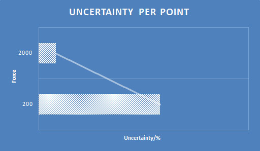
Graph showing the expanded uncertainty becoming larger. In this example, the expanded uncertainty is 0.232 force units at 200 and 0.321 force units at 2000. When one evaluates the expanded uncertainty as a percentage of applied force, the percentage is 0.116 % at 200 and 0.016 % at 2,000. This often demonstrates the need for multiple standards depending on the end user's validation criteria.
For example, using the same contributors for the 200 point in the range. Notice the large contribution of Non-Repeatability Since there was only one run of data we are forced to use Non-Repeatability from the Manufacturer's specification sheet. The Non-Repeatability is of Rated Output, so the same number is used as 0.01 % of 2000 force units which is 0.2 or 0.1 % at the 200 force point. When using a specification sheet, it is important to understand how it is written.
Specified Tolerance
If the laboratory is calibrating to a specified tolerance, then it may not be appropriate to use non-linearity, hysteresis, or SEB. The next Blog may show an example where specified tolerance is used.
Calculating Uncertainty for Force Measuring Devices -Conclusion
Working through this example should further prove the point that these commercial-type calibrations are not very meaningful and there are several gaps missing as it is almost impossible to prove the expected performance of the device without additional testing not supplied with a commercial calibration. Such a test would be the reproducibility of the force device. Without randomizing the loading conditions, one would not know how well the device would repeat.
Using the manufacturer's specifications does not let the end-user know the true performance of their force-measuring device. There is not enough statistical evidence to prove the specification sheets are correct. We have observed several load cells with a non-linearity higher than what the manufacturer claim. The recommendation is to abandon this practice and follow a published standard for your force calibrations like the ASTM E74 one.

If you enjoyed this article, check out our LinkedIn and YouTube channel for more helpful posts and videos.
Everything we do, we believe in changing how people think about force and torque calibration. Morehouse believes in thinking differently about force and torque calibration and equipment. We challenge the "just calibrate it" mentality by educating our customers on what matters and what causes significant errors, and focus on reducing them.
Morehouse makes our products simple to use and user-friendly. And we happen to make great force equipment and provide unparalleled calibration services.
Wanna do business with a company that focuses on what matters most? Email us at info@mhforce.com.
# Calculating Uncertainty for Force Measuring Devices

