

ASTM E74 Calibration Procedure Simplified - Intro
Steps Recommended for Performing Calibration in Accordance with ASTM E74
Stabilization
- Allow UUT to come to room temperature
- Warm-up Instrumentation
Preparation
- Select 10-11 Test points
- IF UUT IS TO BE USED IN BOTH INCREASING AND DECREASING FORCES, THE DEVICE MUST BE CALIBRATED IN BOTH MODES. THE SELECTION OF FORCE POINTS SHOULD BE AT LEAST 21 (11 INCREASING AND 10 DECREASING)
- There should be at least one calibration force for each 10% interval throughout the loading range and if the instrument is to be used below 10% of its capacity a low force should be applied. This low force must be greater than the resolution of the device multiplied by 400 for Class A or 2000 for Class AA devices
Calibration Procedure
- Fixture UUT in Test Frame
- Exercise UUT 2-4 times
- Apply 1st series of forces (Run1)
- Rotate the UUT 120 degrees if possible for run 2
- Apply 2nd series of forces (Run2)
- IF UUT IS COMPRESSION AND TENSION SWITCH TO OTHER MODE AFTER FINISHING RUN 2 AND EXERCISE AND REPEAT THE ABOVE STEPS
- For Tension and Compression calibration, intersperse the loadings. Be sure to re-exercise the UUT prior to any change in setup
- Rotate the UUT another 120 degrees if possible for run 3
- Apply 3rd series of forces (Run3)
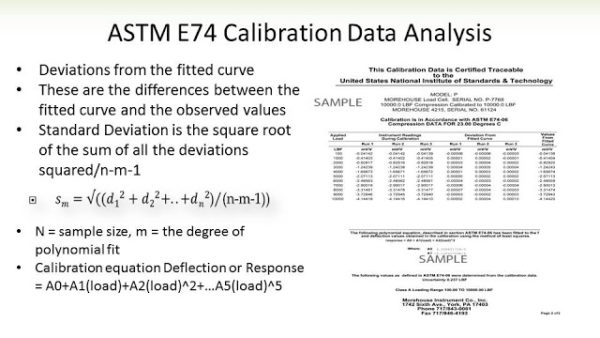
Data Analysis
- Deflection calculation Methods
Method B Deflection readings should be calculated as the difference between readings at the applied force and the average or interpolated zero force readings before and after the applied force readings.
Method A Deflection readings are calculated as the difference between the deflection at the applied force and the initial deflection at zero force.
Criteria for Use of Higher Degree Curve Fits
The resolution must exceed 50,000 counts
An F distribution test is used to determine the appropriate best degree of fit (instructions for this test can be found in the Annex A1 of the ASTM E74 Standard)
Criteria for Lower Load Limit
LLF = 2.4 * STD DEV – This corresponds to a 98.2 % Coverage Factor
Based on LLF or Resolution whichever is higher
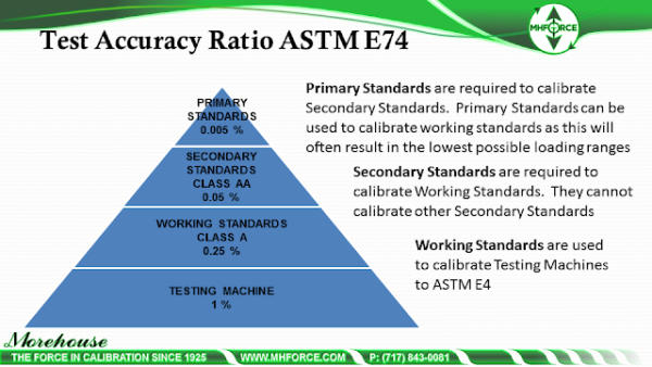
Class A 400 times the LLF or resolution
Class AA 2000 times the LLF or resolution
NOTE: Any instrument that is either modified or repaired should be recalibrated
Recalibration is required for a permanent zero shift exceeding 1.0 % of full scale
Calibration Interval Determination
- Secondary Standards should be calibrated to ensure that they do not change more than 0.032 % over the loading range
- Instruments used as Class A devices (Typically used to calibrate testing machines) should be calibrated to ensure that they do not change more than 0.16 % over the loading range.
Note: Any device not meeting the stability criteria shall be recalibrated at intervals that shall ensure the stability criteria are not exceeded during the recalibration interval. - If the Calibration device is stable to within 0.16 % over the loading range, then the calibration interval can be 2 years as long as the UUT continues to meet the stability criteria
ASTM E74 lower load limits matter
There are two rules to remember when calibrating to ASTM E74:
- The Class A or Class AA loading range can’t be less than the first applied non-zero force point
Per Section 8.6 of ASTM E74-13a: “The loading range shall not include forces outside the range of forces applied during the calibration.”
Per Section 7.2.1: “If the lower limit of the loading range of the device (see 8.6.1) is anticipated to be less than one-tenth of the maximum force applied during calibration, then forces should be applied at or below this lower limit.”
- Zero can’t be a test point
Per Section 7.2.1 of ASTM E74-13a, “In no case should the smallest force applied be below the lower limit of the instrument as defined by the values: 400 x resolution for Class A loading range and 2000 x resolution for Class AA loading range.”
ASTM E74 Calibration Procedure Simplified - Outro
This post covers the basics. Anyone calibrating in accordance with the ASTM E74 standard should purchase a full copy of the standard here http://www.astm.org/Standards/E74.htm
Morehouse Developed a Calibration and Measurement Capability worksheet for instruments calibrated in accordance with the ASTM E74 standard. This sheet can be downloaded at http://www.mhforce.com/s/CMC-CALCULATIONS-FOR-FORCE-MEASUREMENTS.xlsx
If you enjoyed this article, check out our LinkedIn and YouTube channel for more helpful posts and videos.
Everything we do, we believe in changing how people think about force and torque calibration. Morehouse believes in thinking differently about force and torque calibration and equipment. We challenge the "just calibrate it" mentality by educating our customers on what matters, and what causes significant errors, and focus on reducing them.
Morehouse makes our products simple to use and user-friendly. And we happen to make great force equipment and provide unparalleled calibration services.
Wanna do business with a company that focuses on what matters most? Email us at info@mhforce.com.
# ASTM E74 Calibration Procedure

